Version: 13. Sepe,mer 2004
8
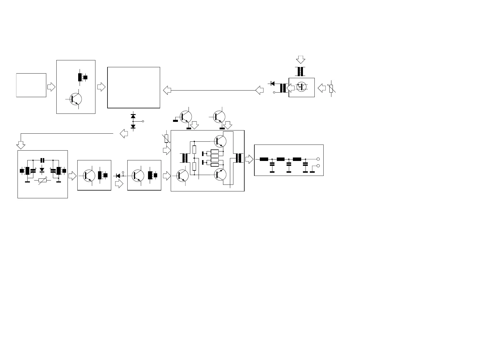
8. Transmitter:
The transmission frequency is obtained by mixing the 8 MHz signal with the
LO signal. M1 works as a transmitter mixer with changed siganl direction.
The signal at the RF port is coupled via PIN diodes D6-D7 and C35 to the
input bus of the preselector filter, now working as a transmitter prefilter.
The high selectivity of the filter reduces unwanted signals from the mixer.
The filtered output signal is led via the output bus over C36 to T9, the
transmitter preamplifier. The 18 dB signal at Tr1 is led via PIN diode D3 to
the predriver at T3. The stage amplification is chosen to be able to drive
the two stage PA fully. Tr3 serves to impedance match T3 to T5. The circuit
at T5-T6-T7 is a slightly modified DL-QRP-PA:
The PA quiet current is adjustable by P1, and independent of the
board voltage.
The push-pull stage uses robust 2SC1969’s with a large collector
current reserve, given good intermodulation characteristics.
The ferrite volume of Tr5 is enlarged to reduce distorsion due to
TR7 1:2
power adj ust
TR 6 2 : 1
PIN 30 KEY I N
PIN 31 +10VS
D1 4
T23
Mischer TUF1
LO
Local Oscill ator
T10
TR2 2: 1
31+10VS
D7
D6
T9
TR1
Bandfilter Bandmodul
Abs timmspannung
Preselektor
35 +10VS
T3
TR3
T5
1R
1R
1R
1R
Tr.4
T6
T7
Tr.5
1
2
3
4
1
2
3
4Wdg
2Wdg 2Wdg
2Wdg
5Wdg
+ 13,8V
+10VS
L4 L5 L6
52
51
Ant enne
Ti efpassfi lter
T4
Io Komp T5
T8
Io Komp T6/7
P1 Io PA
saturation
The transmitter is followed by a 3 stage Chebychef low pass filter with a cut
off frequency of 33 MHz, to reduce harmonics in the BC/TV bands by more
than 60 dB. The in band variation is a maximum of 0,3 dB. The band 80 to
17 meters, this should be followed
by the electronically switched
output filter, developed for the
“Tramp”, to reduce emissions in
higher ham bands. D11 works as a
measuring rectifier for the relative
power output meter. To avoid un-
controlled feed back in the trans-
mitter, the decoupling between
transmitter output and the T/R
switch diode should be at least 70
dB. Experiments with electronic
switching showed problems with
the high RF voltage (up to 70 Vpp).
As the switch carries no RF current
(only active during reception), the
choice was a small DIL Reed relay,
which also allowed shorting the the
[Übersprechsignal - please
change!!], in a painless way. The
attack time of the relay is only some 0.5 mSec. The life time at some 10
million cycles. Thanks to the low weight of the moveable parts, no clicks
are heard.
9. CW logic, T/R switching:
Pin 2 of the CPU (IC7) is bidirectional, having the following functions:
During reception pin 2 is kept at high potentil by an internal pull up resis-
tor. When the integrated keyer is activated, pin 2 is pulled low in the rhytm
of the CW signal. Synchronously pin 15 of IC7 generates a side tone. And
further an optional RIT/XIT is activated.
When the internal keyer isn’t used, external keying is possible. In this mode
pin 53 is grounded via R103-D31 in keying rhytm. In SSB mode the PTT
keys the same pins, but T18/T19 quiets the side tone input at IC11.