Version: 13. September 2004
43
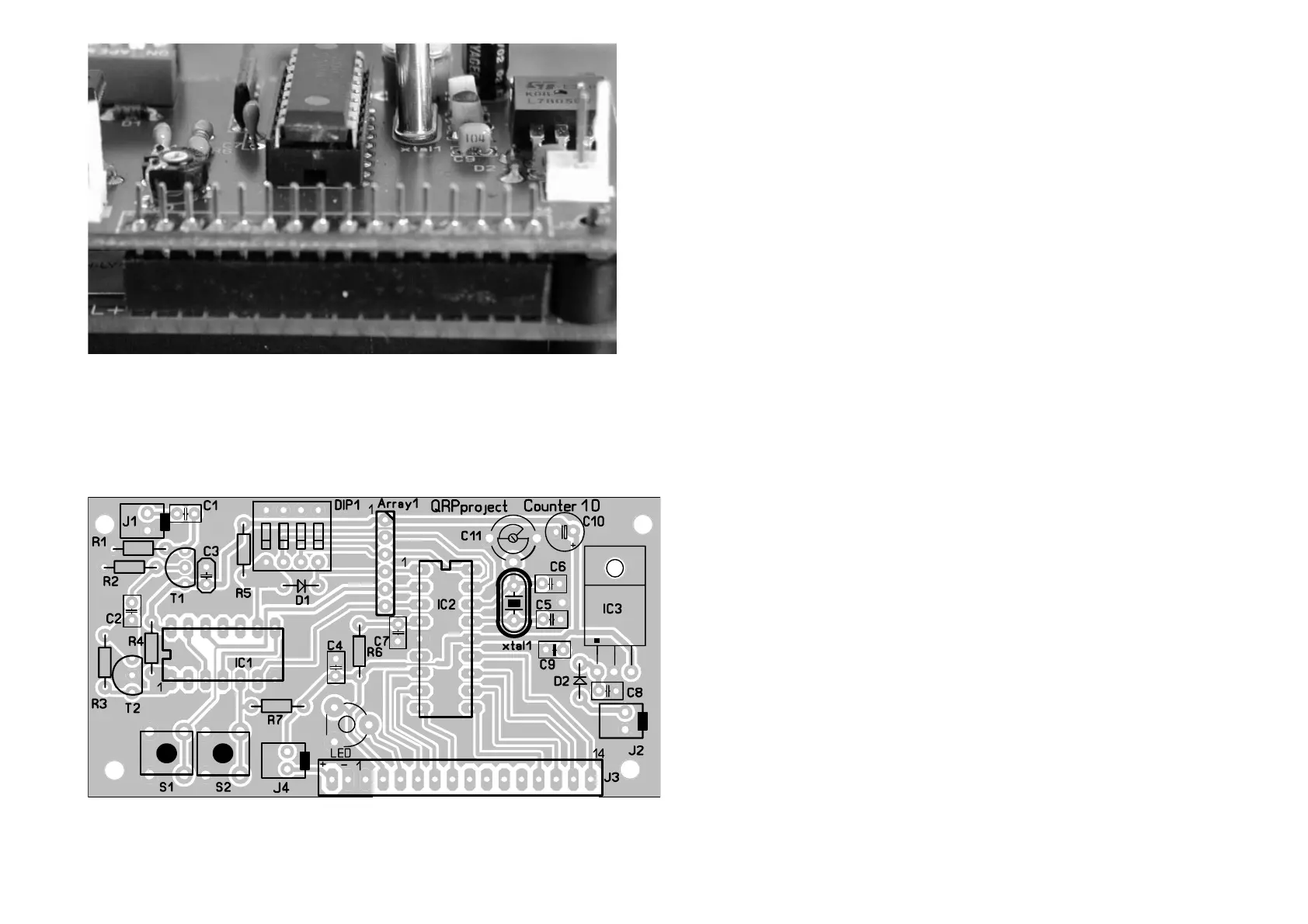
[ ] J14 PCB connector 16 pins
On the backside of the display the 16 pin connector will be soldered as
shown on the drawing.
Display and counter may now be plugged together and tightened with
screws and distance bolts to one unit.
Terminator J2 will be connected to +12 Volts and ground, coming from the
basic unit. J4 is connected to the display backlight switch and J1 is the RF
input-termination.
If +12 Volts are connected, first contrast of the display should be adjusted
using the trimming potentiometer that way, that the characters are readab-
le pretty good.