46
1001108-01-F
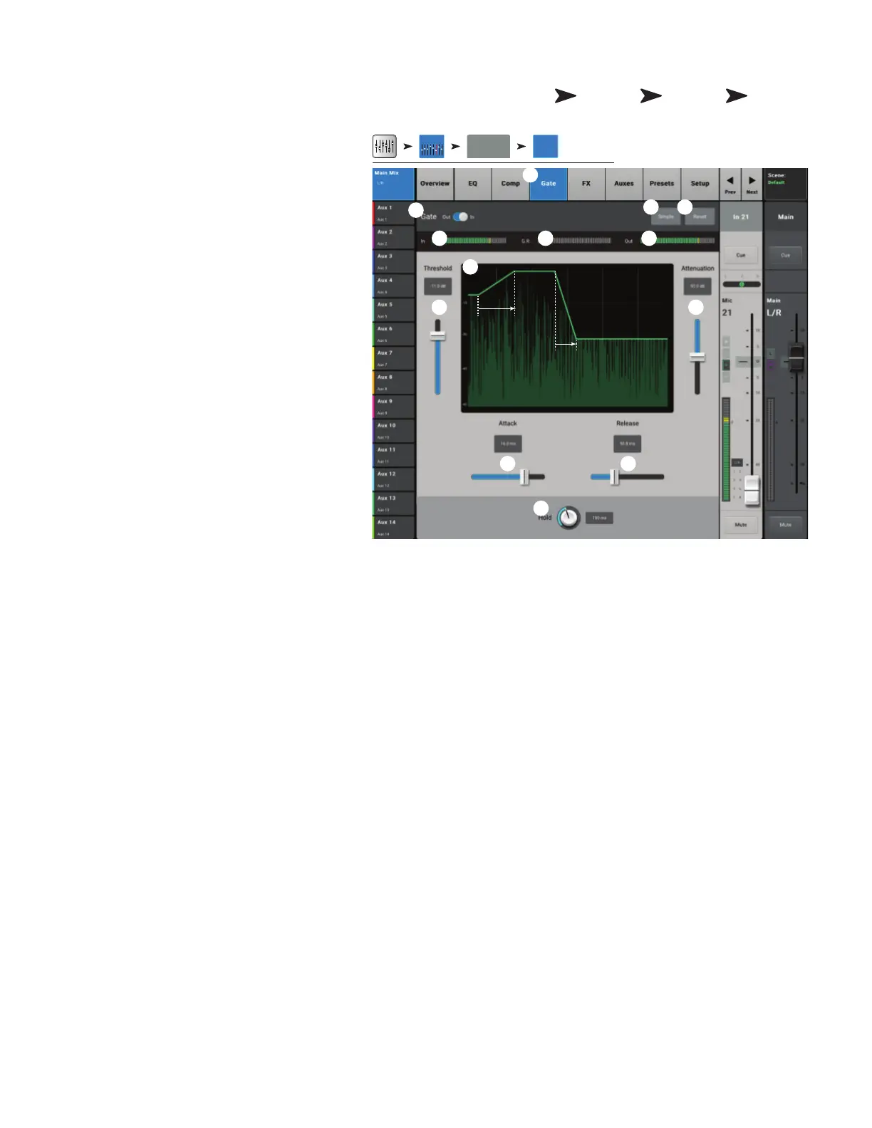
I C − G
The Gate passes audio above a set Threshold, and
attenuates audio below the Threshold.
1.
Gate tab
– Selects the Gate Screen.
2.
Gate In switch
– Engages or disengages
the Gate.
3.
Simple button
– Turns Simple mode on
and off. Hides all controlsexcept:
• Gate In button
• Simple button
• Reset button
• Gating knob
4.
Reset button
– Sets all the Gate controls
to their factory default position.
5.
In meter –
RMS input level
6.
G.R. meter –
Gain Reduction – indicates
how much the signal is being reduced by the
Gate.
7.
Out meter –
Output level
8.
Threshold slider
– Sets the point at which
the Gate allows audio to pass.
9.
Gate graph
– When the Gate is engaged,
the trace turns green.
• Threshold (A)
• Attack time (A-B)
• Release time (C-D)
• Attenuation Level (E).
10.
Attenuation slider
– Sets the amount of attenuation applied to the output when the signal is below the Threshold.
11.
Attack slider
– Adjusts how quickly the gate reacts to a signal that exceeds the threshold.
12.
Release slider
– Adjusts how quickly the Gate attenuates the audio when signal falls below threshold.
13.
Hold knob
– Sets the minimum time the Gate stays open once it is opened, and the length of time the Gate stays open after the
input level drops below the Threshold.
Home
Touch an
Input Bank
Touch a
Channel
Select
Gate
Tab
Inputs 1-8
In 1 Gate
Inputs 1-8
2
3
1
6
9
8
5 7
10
4
11 12
13
A B
DC
E