August 1, 2018 7014-285C 23
CB1200 Pellet Insert
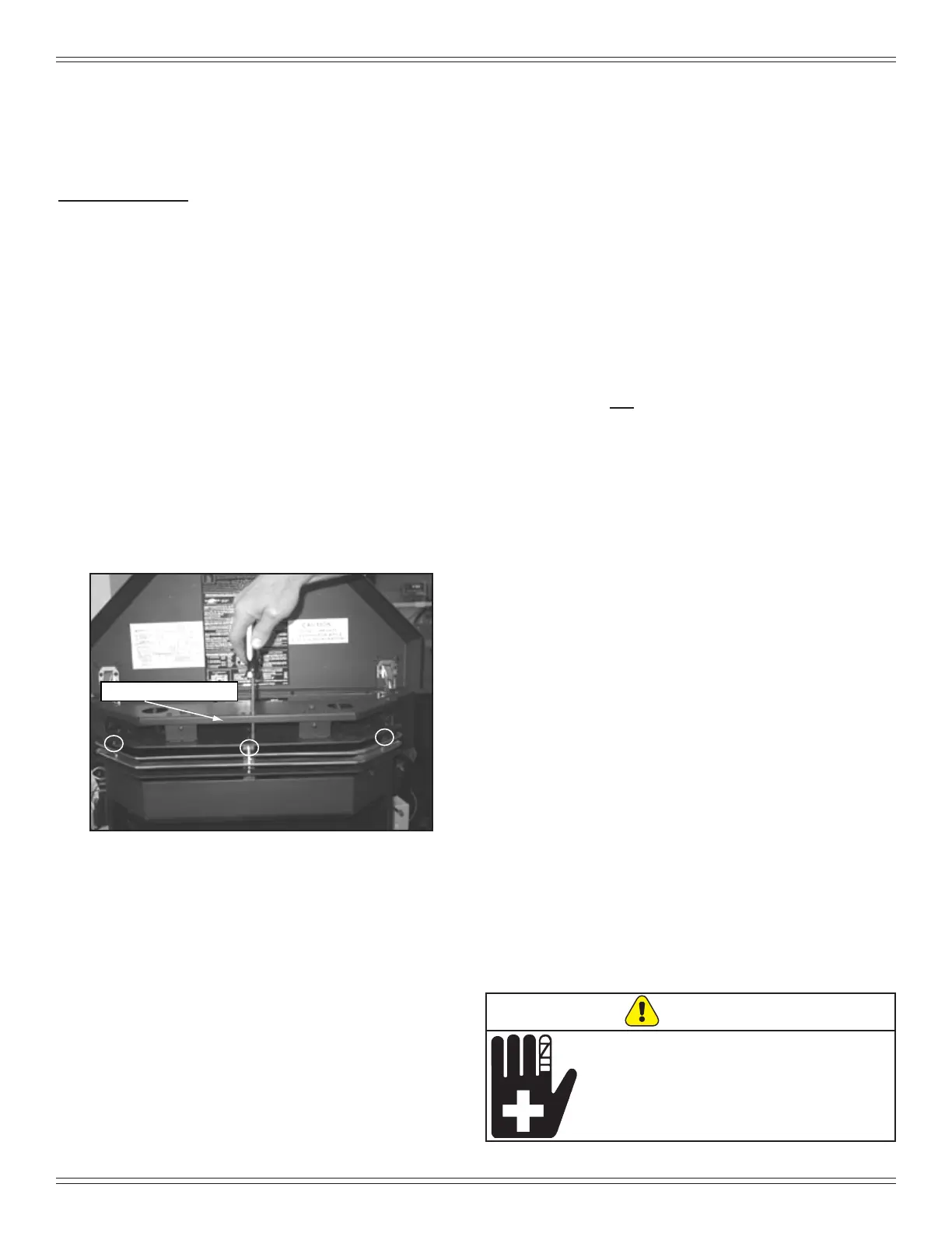
D. Grill Installation
Figure 23.1
1. Remove grill from packaging.
2. Lift top up.
3. Align the 3 holes in the insert with the holes in the grill.
4. Use a Phillips screw driver to secure in place. It will
be necessary to go through the hole in the bag support
shelf to gain access to the screw. Figure 23.1.
5. Lower the top into position.
C. Adjustable Hopper Options
Depending on your installation, the hopper can be adjusted
down 2-1/2 inches (64mm) and will decrease in capacity
from 75lbs to 60lbs.
To adjust hopper:
1. Using a Phillips head screw drive, remove all the
screws from the top of the hopper securing the top
hopper piece to the bottom hopper piece and insert
body.
2. Adjust downward 2-1/2 inches (64mm).
3. Mark location for new holes and drill new holes.
4. Secure hopper pieces together using screws removed
in step one.
5. See drawing on page 8, Figures 8.1 and 8.2.
E. Adjustable Hearth Support
Size: 9”D x 45”W, 2” to 10” Height Adjustment
Included in Kit: (1) trim top, (1) trim front, (2) trim sides,
double-sided tape (already installed)
Tools Needed: Phillips head screw driver, sheet metal
shears, measuring tape, gloves
1. The 10 screws on each set of scissors will already be
loose when shipped. Figure 24.1 on page 24.
2. Expand scissors to desired height. Tighten screws to
hold in place using Phillips head screw driver. Figure
24.2
on page 24
.
3. Measure front and side trims to required height to
cover scissors and mark pieces for cutting. Cut excess
material from top of trims edge, not bottom. This
edge will be sharp; wear gloves to prevent injury to
your hands. Figure 24.3 on page 24.
4. Using sheet metal shears, cut trim along the marked
edge. The cut edge ts under lip of top trim, so it
allows for some variance in your straight edge.
5. The double-sided tape that holds front and side
trims to scissors has a powerful bonding adhesive.
Adjustments are extremely dicult once trim has
adhered to tape. Do a dry run rst without removing
paper from tape.
6. Place cut edge of trim under top lip and into position
on scissors. Place side pieces on rst and then front
piece. The front piece overlaps side pieces.
7. Once you are satised with the positioning, remove
trim and set aside.
8. Remove the paper from double-sided tape that is
to accept trim side. Align side and then press hard
against tape to secure side piece. Repeat for other
side. Install front trim piece last.
9. There are 3 holes in the back ange of the top to
secure it to the wall if necessary. Use the appropriate
fastener for the type of wall material, i.e., brick, sheet
rock, etc.
NOTE: 3/8 inch (9.5mm) thick tile or like material can be
cut to size and t under lip of top trim edge for a
decorative touch. Figure 24.3 on page 24.
WARNING
Sheet metal trim edges will be sharp.
For safety purposes wear gloves.
Injury can occur.