GARNET DIRECT VENT ROOM HEATER
250-6443B October 7, 2003 Page 29
GARNET DIRECT VENT ROOM HEATER
250-6443B October 7, 2003 Page 30
Step 1.
Before cutting any holes, assemble the desired sections
of direct vent pipe to determine the center of the masonry
penetration.
Step 2.
Once the center point of the penetration has been determined,
cut a 6” (152mm) diameter hole in the masonry. If the hole
is too large, the retro connector might not mount properly; if
the hole is too small, the appliance might starve for intake air.
If there is a frame wall in front of the masonry wall, cut and
frame a 10” (254mm) square opening in the wall (centered
around the 6” (152mm) masonry opening). If there is sheet
rock only (no studs) in front of the masonry the 10” (254mm)
opening is still needed, but does not need to be framed. If the
hole is framed a wall thimble is required. This allows the retro
connector to mount directly on the masonry and provide the
correct clearances to combustibles (Fig. 22).
VERTICAL INSTALLATION
INSTALLATION INTO AN EXISTING MASONRY CHIMNEY (USA ONLY)
10" x 10" FRAMED
OPENING IN WALL
STUDWALL
MASONRY
CHIMNEY
RETRO
CONECTOR
(4) MASONRY BOLTS
(NOT INCLUDED)
WALL THIMBLE
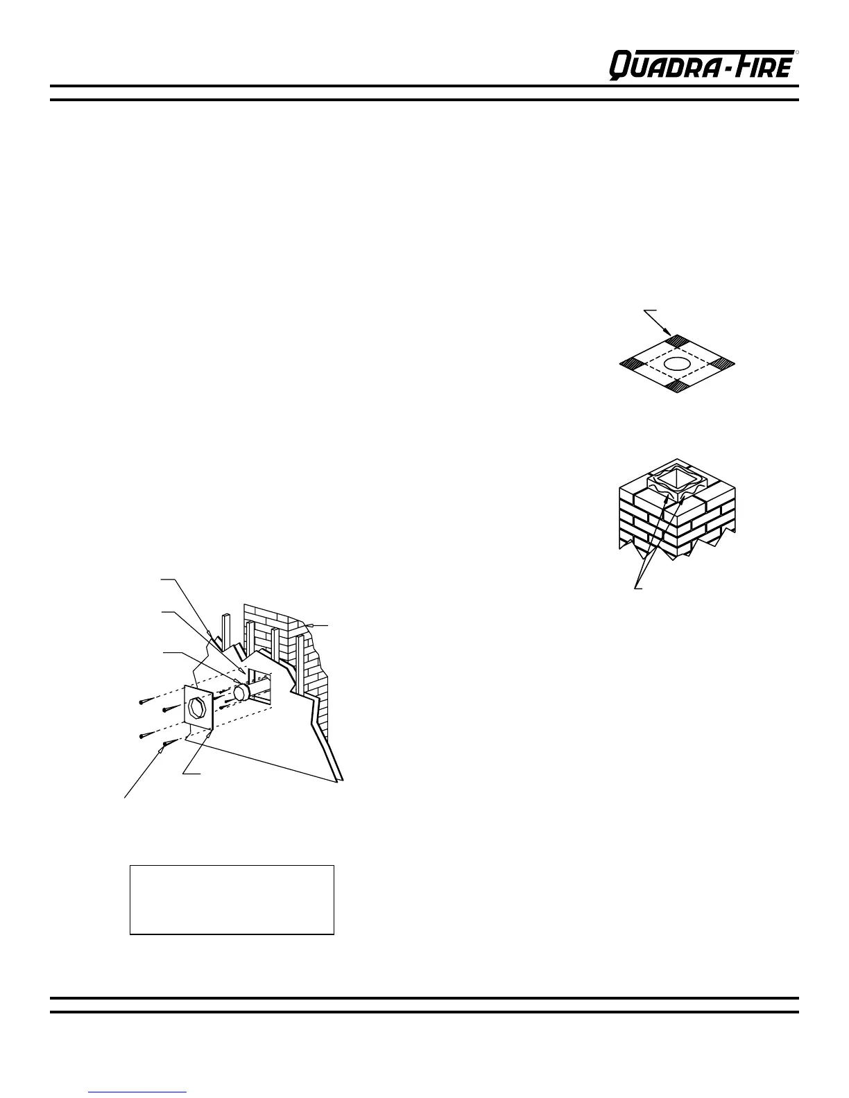
Step 3.
Secure the flashing (SDV
#705C) to the top of the
masonry chimney using a bead
of non-hardening sealant-
adhesive. If the flashing is
larger than the top of the
chimney, cut and fold flashing
as needed to fit chimney (Fig.
23).
Step 4.
To determine the length of
flex needed, measure from 3”
(76mm) above the top of the
flashing down to the level of
the opening. Add the distance
from the center of the chimney
out through the wall. Cut a
piece of 4” (102mm) flex to this
length (extended to its nominal
length). Be sure to leave 2”-3”
(51mm-76mm) of flex above
the existing chimney to allow
for connection to the
termination kit.
Step 5.
Connect the flex liner to the top adapter using three (3)
sheet metal screws (Fig. 19, page 29).
Step 6.
Feed the flex liner through the flashing into the chimney.
Carefully feed the flex liner down the chimney to the bottom
and out the opening in the masonry wall, forming an angle to
line up the flex liner with the vent opening on the appliance.
WARNING: Do not let the flex liner sag below the level at
which it will connect to the appliance or connector. This
could allow hot gas to become trapped and potentially
become a fire hazard. The flex liner path should always
be sloped up toward the termination cap.
FIG. 22
FIG. 23
NOTE: FOR HEARTH APPLICATIONS
REFER TO PAGE 19 FOR THE USE
OF THE 923GCL CO-AXIAL TO CO-
LINEAR APPLIANCE CONNECTOR.
CUT AND BEND
FLASHING AS NEEDED
TO FIT CHIMNEY
SEALANT-ADHESIVE