QXS-4 Series Specifications 19
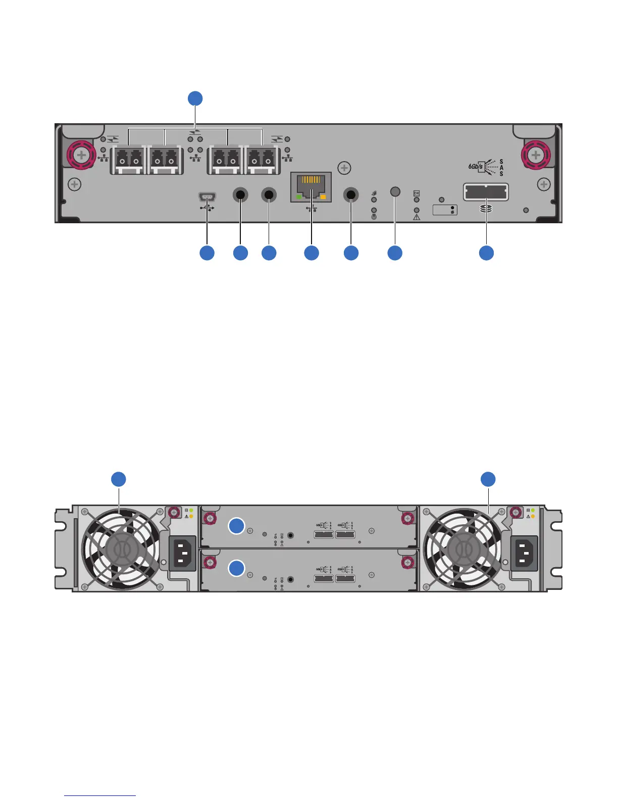
Figure 16 provides the controller I/O module (with ports identified).
Figure 16 Controller I/O Module
12, 24, and 48 Drive Expansion Chassis: Rear Panel Components
Figure 17 provides the 12, 24, and 48 drive expansion chassis (rear panel components).
Figure 17 Expansion Chassis: Rear Panel Components
LINK SERVICE–1
CACHE
DIRTY
CLEAN
LINK
ACTSERVICE–2 CLI
CLI
PORT 0 PORT 1
PORT 2 PORT 3
1
2 3 4 5
6
7 8
1 CNC FC or iSCSI SFP+ Ports (used for host
connection or replication)
2 CLI Port (USB - Type B)
3 Service Port 2 (Service Personnel Use Only) 4 Reserved for future use
5 Network Port 6 Service Port 1 (Service Personnel Use Only)
7 Disabled button (used by engineering only) (Sticker
shown covering the opening)
8 mini-SAS expansion port
LINKLINK
SERVICE
TUONI
LINKLINK
SERVICE
TUONI
1 Power supplies (AC shown) 2 Expansion I/O Module A
3 Expansion I/O Module B
 Loading...


