GL300 User Manual
TRACGL300UM001 - 8 -
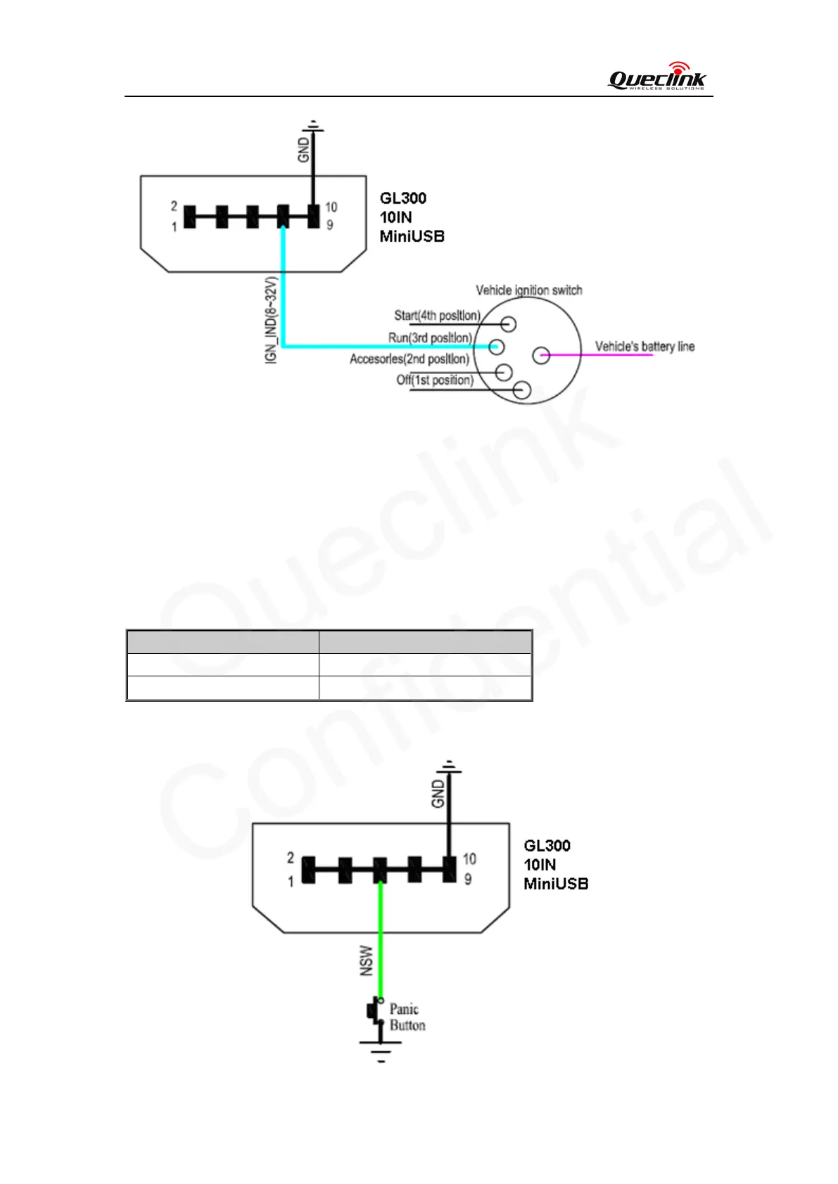
Another easy way is to connect PIN7 to a power output in the fuse box of the vehicle which is
only enabled after the vehicle is ignition on. For example: the power output for radio FM.
2.6. External Input Interface
The Pin 5 on Mini-USB connector is a negative trigger input in newer hardware version. It is
named as NSW pin.
For negative trigger input the electrical conditions are:
Logical State Electrical State
Active 0V to 0.8V
Inactive 1.7V to 32V or Open
An input example is shown as following figures:
 Loading...