EasyManua.ls Logo

Queclink GL320M Series - Interface Definition

Queclink GL320M Series
17 pages
Print Icon
To Next Page IconTo Next Page
To Previous Page IconTo Previous Page
Loading...
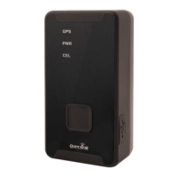
GL320M Series User Manual
QSZTRACGL320MUM0100 6
3. Interface Definition
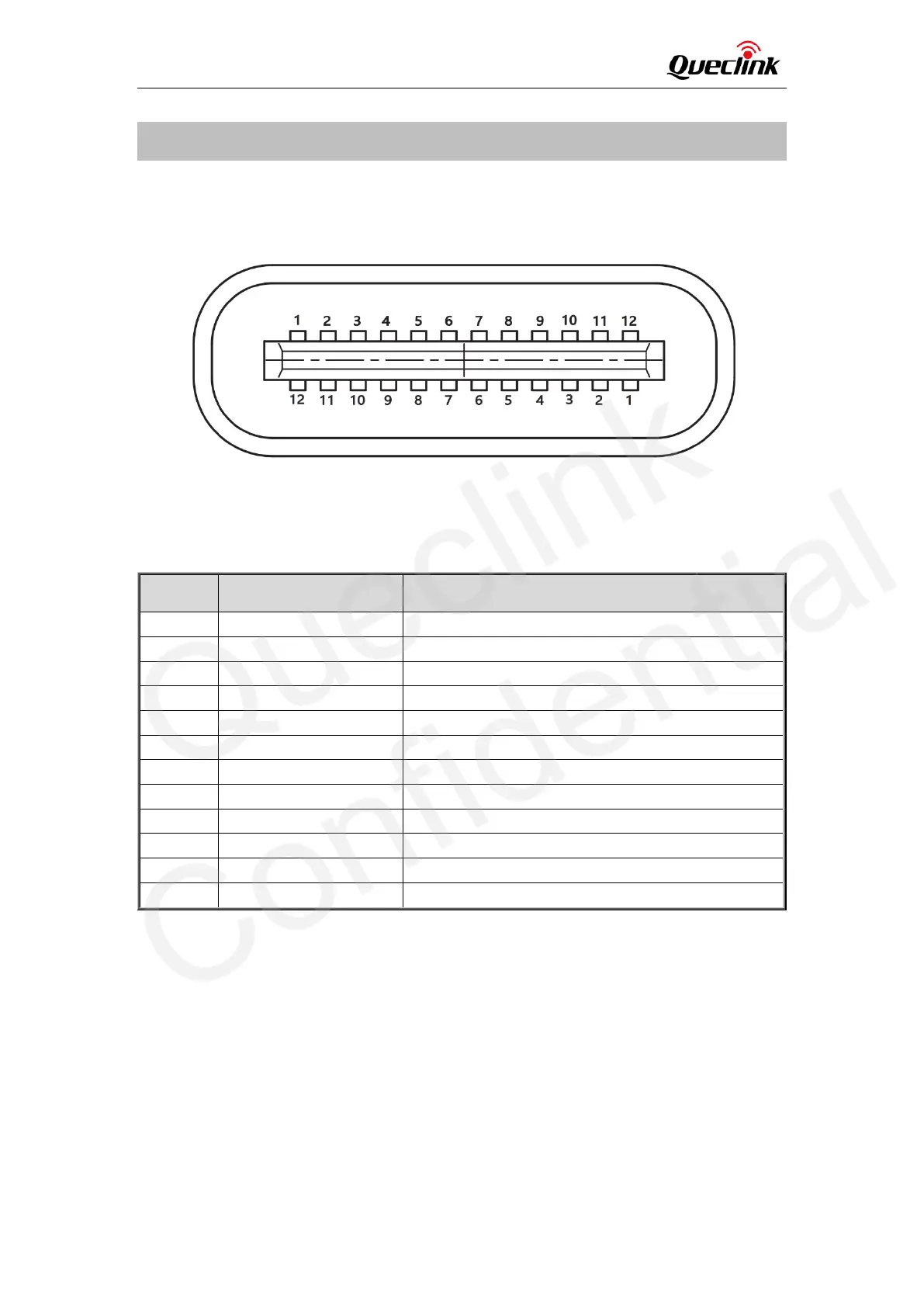
The GL320M has a 12-pin (two sides) Type-C interface which contains the connections for power,
ignition detection, input, etc. The sequence and definition of the 24-pin connector are shown in
the following figure:
Figure 3. 12-pin (two sides) Type-C Interface of the GL320M
Table 7. Description of 24-pin Connections
Pin No.
Pin Name
Function Description
1
GND
Power GND
2
IN1
Negative input1
3
IGN Input/ADC_IN1
The ignition input(0--24V)/PT100 AD Output (0--3.0V)
4
VBUS
USB+5.0V
5
CC1
Charging protocol
6
USB DP
LTE module USB DP
7
USB DM
LTE module USB DM
8
EXTBAT /VDD OUT
External battery input/3.0--3.9V Output
9
VBUS
USB+5.0V
10
UART_RXD
Debug Receive Data
11
UART_TXD
Debug Transmit Data
12
GND
Power GND
Queclink
Confidential

Related product manuals