GMT200 User Manual
TRACGMT200UM001 - 9 -
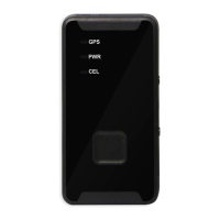
2.2. Parts List
Table 3: Part List
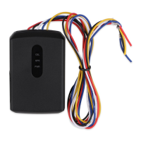
Name Picture
GMT200 Locator
DATA_CABLE_M(Optional)
2.3. Interface Definition
There are 5 wires on GMT200 User Cable which contain the connection for power, ignition
input, digital input, digital output etc. The user cable’s definition is shown in following table.
Table 4: Description of GMT200 User Cable
Index Colour Description Comment
1 Red Power External DC power input,9-32V
2 Black Ground System ground
(connect to the vehicle’s frame directly)
3 White Ignition Ignition input, positive trigger
4 Blue Digital input Digital input, negative trigger
5 Yellow Digital output Digital output ,low side 150mA max with latch