GV75WUserManual
TRACGV75WUM001
‐11‐
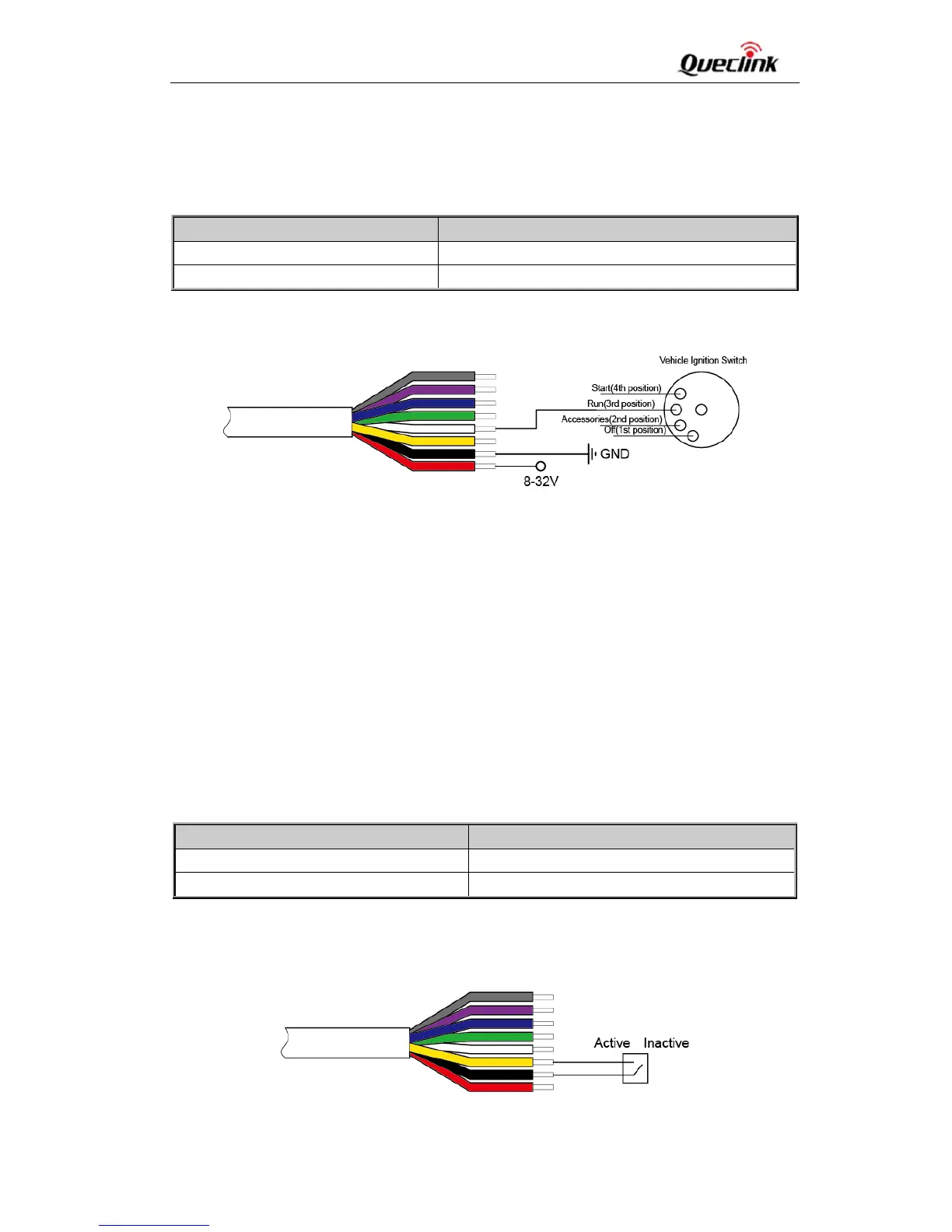
Figure2:TypicalPowerConnection
3.4. IgnitionDetection
Table6:ElectricalCharacteristicsofIgnitionDetection
Figure3:TypicalIgnitionDetection
The white wireis used for ignition detection. It isstronglyrecommended to connect this wire to
ignitionkeyat“RUN”positionasshownabove.
Analternativetoconnectingtotheignitionswitchistofindanon‐permanentpowersource(likethe
powersourceforFMradio)thatisonlyavailablewhenthevehicleisrunning.Ignitionsignalcanbe
configuredtostarttransmittinginformationtothebackendserverwhenignitionisonandtoenter
powersavingmodewhenignitionisoff.
3.5. DigitalInput
ThereisanegativetriggerinputonGV75W.Fornegativetriggerinput,theelectricalconditionsare
asfollows:
LogicalState ElectricalState
Active 0Vto0.8V
Inactive 1.7Vto32VorOpen
Table7:ElectricalConditionsofNegativeTriggerInputs
Theconnectionisshownasfollows:
Figure4:ConnectionforNegativeTriggerInputs
LogicalStatus ElectricalStatus
Active 5.0Vto32V
Inactive 0Vto3Voropen