GV75WUserManual
TRACGV75WUM001
‐12‐
3.6. DigitalOutput
TheoutputsareOpen‐Draintypewithnointernalpull‐upresistorwhichcanbeusedtocontrolarelay.
Itmeansthattheuserhastoconnectapull‐upresistororarelaycoilbetweentheoutputpinand
any positive voltage (32V max) to generate correct output. Eachoutputcandriveacontinuous
currentof0.15A.
Thegreenwireislowside150mAmax,andthebluewireislowside150mAmaxwithlatch.
Theelectricalconditionsareshowninthefollowingtable:
Table8:ElectricalConditionsofDigitalOutputs
Note:
Therelayoutputcanbelatchedbythesoftware,soeveniftheGV75Wisrestartedorpowereddown
insomecases,therelayoutputwillnotchange.Tousethelatchfunction,themainpowerandbackup
batteryshouldbeconnected.Otherwisetherelaywillalwaysbeinnormallyclosedstate.
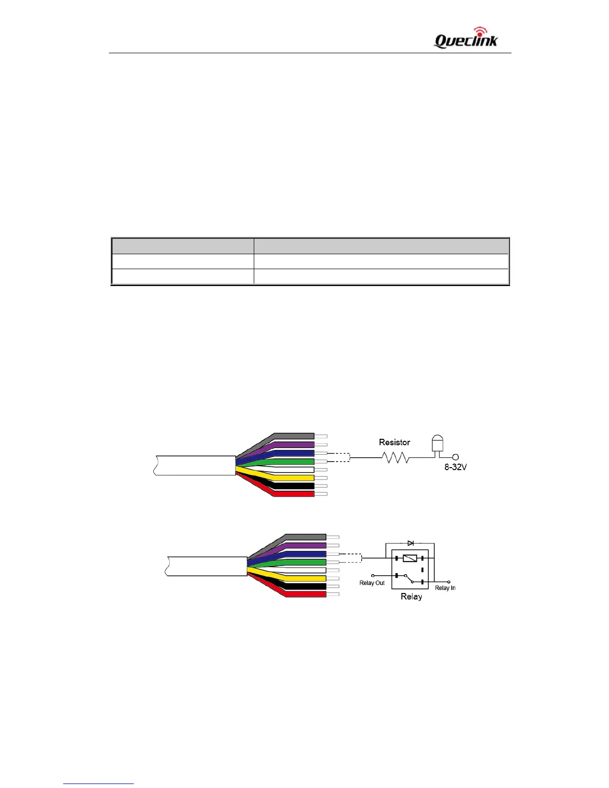
Digitaloutputsareusedforcutting/restoringGND.Theconnectionsareshownbelow.
Figure5:ConnectiontoDriveanLED
Figure6:ConnectiontoDriveaRelay
Note: Alloutputsare internally pulled up to PWRpinby a diode. Sonoexternalflybackdiodeis
neededwhentheoutputisconnectedtoaninductiveload.
LogicalState ElectricalState
Enable <1.5V,drivecurrentis0.15A
Disable Openorthepull‐upvoltage(max32V)