NB-IoT Module Series
BC65 Hardware Design
BC65_Hardware_Design 36 / 55
4.1.2. Antenna Reference Design
BC65 provides an RF antenna pad for external NB-IoT antenna connection.
⚫ The RF trace on the host PCB connected to the module’s RF antenna pin should be coplanar
waveguide or microstrip, whose characteristic impedance should be close to 50 Ω.
⚫ BC65 comes with ground pins which are next to the antenna pin to give a better grounding.
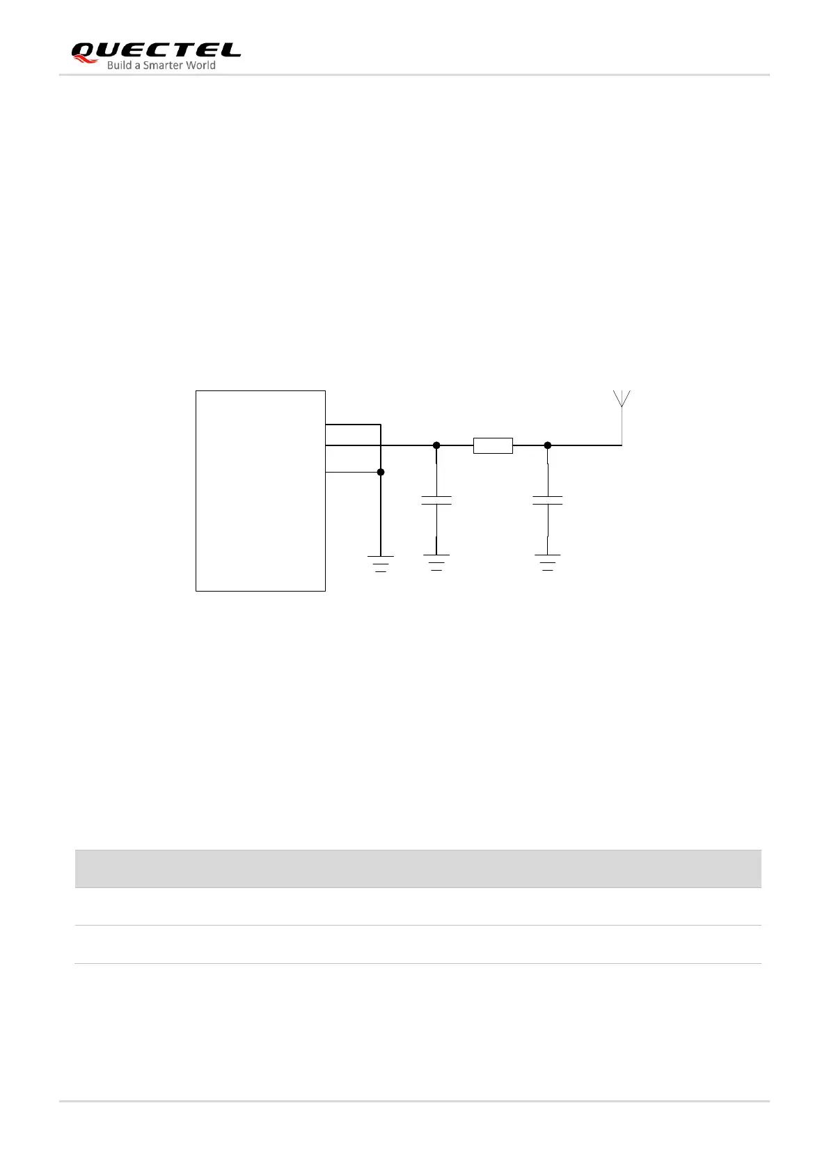
⚫ To achieve better RF performance, it is recommended to reserve a π-type matching circuit and place
the π-type matching components (R1/C1/C2) as close to the antenna as possible. By default, the
capacitors (C1/C2) are not mounted and a 0 Ω resistor is mounted on R1.
Reference design for the NB-IoT antenna interface is shown as below.
Figure 23: Reference Design for NB-IoT Antenna Interface
4.1.3. Antenna Requirements
To minimize the loss on RF trace and RF cable, pay attention to the antenna design. The following tables
show the requirements for the antenna.
Table 18: Antenna Cable Insertion Loss Requirements