EasyManuals Logo
Home>Quectel>Control Unit>EG06 Series

Quectel EG06 Series User Manual

Quectel EG06 Series
97 pages
To Next Page IconTo Next Page
To Previous Page IconTo Previous Page
Page #50 background imageLoading...
Page #50 background image
LTE-A Module Series
EG06 Hardware Design
EG06_Hardware_Design 48 / 89
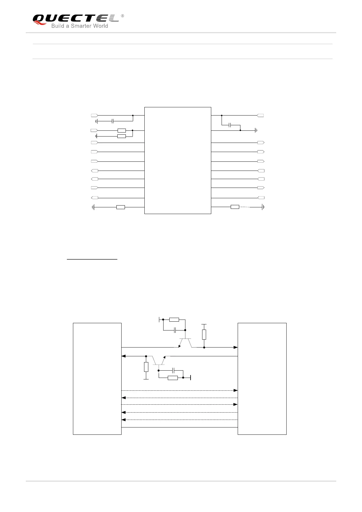
The module provides 1.8V UART interface. A level translator should be used if the application is equipped
with a 3.3V UART interface. A level translator TXS0108EPWR provided by Texas Instruments is
recommended. The following figure shows a reference design.
VCCA VCCB
OE
A1
A2
A3
A4
A5
A6
A7
A8
GND
B1
B2
B3
B4
B5
B6
B7
B8
VDD_EXT
RI
DCD
RTS
RXD
DTR
CTS
TXD
51K
51K
0.1uF
0.1uF
RI_MCU
DCD_MCU
RTS_MCU
TXD_MCU
DTR_MCU
CTS_MCU
RXD_MCU
VDD_MCU
Translator
VDD_EXT
10K
120K
Figure 21: Reference Circuit with Translator Chip
Please visit http://www.ti.com for more information.
Another example with transistor translation circuit is shown as below. The circuit design of dotted line
section can refer to the design of solid line section, in terms of both module input and output circuit
designs, but please pay attention to the direction of connection.
MCU/ARM
TXD
RXD
VDD_EXT
10K
VCC_MCU
4.7K
10K
VDD_EXT
TXD
RXD
RTS
CTS
DTR
RI
RTS
CTS
GND
GPIO DCD
Module
GPIO
EINT
VDD_EXT
4.7K
GND
1nF
1nF
Figure 22: Reference Circuit with Transistor Circuit
V
OH
1.35
1.8
V

Table of Contents

Questions and Answers:

Question and Answer IconNeed help?

Do you have a question about the Quectel EG06 Series and is the answer not in the manual?

Quectel EG06 Series Specifications

General IconGeneral
BrandQuectel
ModelEG06 Series
CategoryControl Unit
LanguageEnglish

Related product manuals