EasyManuals Logo

Quectel EG915U Series User Manual

Quectel EG915U Series
92 pages
To Next Page IconTo Next Page
To Previous Page IconTo Previous Page
Page #45 background imageLoading...
Page #45 background image
LTE Standard Module Series
EG915U_Series_Hardware_Design 44 / 81
Module
USIM_VDD
GND
USIM_RST
USIM_CLK
USIM_DATA
USIM_DET
0R
0R
0R
VDD_EXT
51K
100 nF
GND
GND
33 pF 33 pF 33 pF
VCC
RST
CLK
IO
VPP
GND
GND
USIM_VDD
15K
(U)SIM Card Connector
Switch
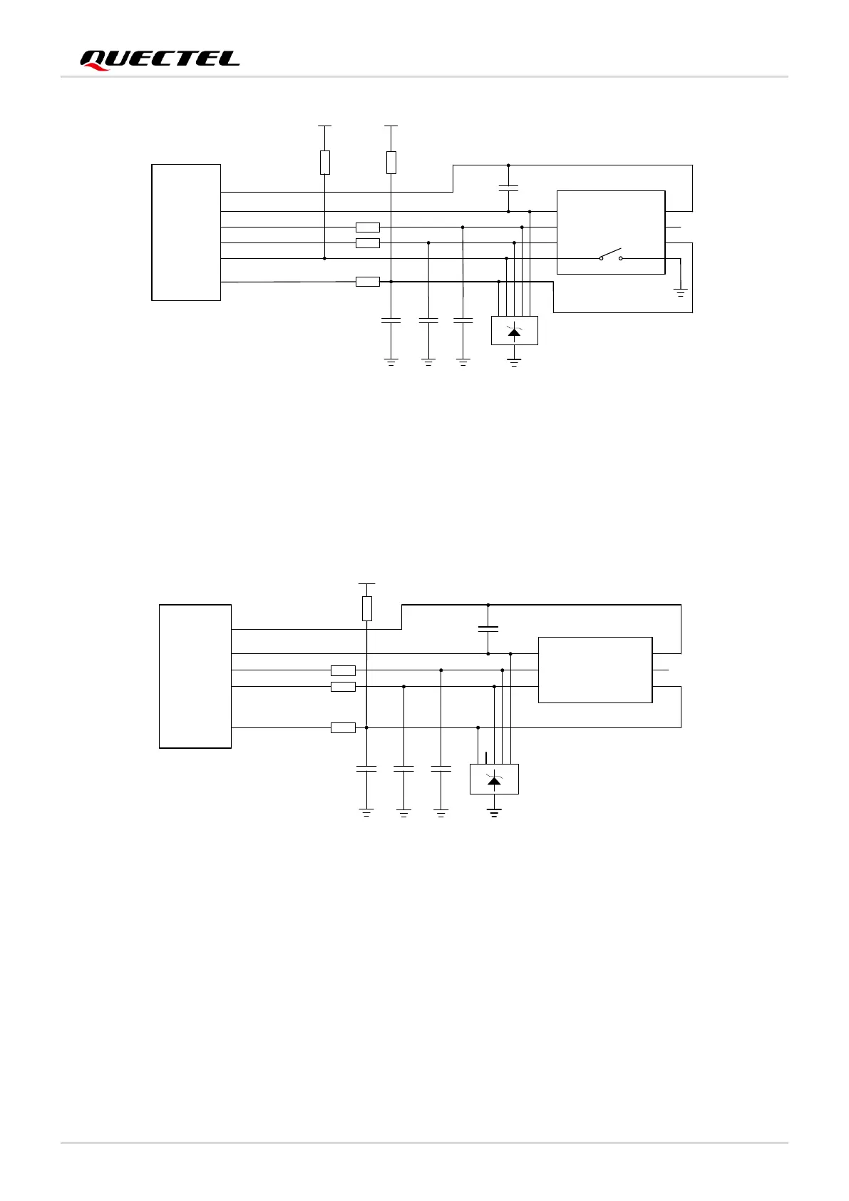
Figure 20: Reference Circuit of (U)SIM Interface with an 8-Pin (U)SIM Card Connector
If (U)SIM card detection function is not needed, please keep USIM_DET unconnected. A reference circuit
for (U)SIM interface with a 6-pin (U)SIM card connector is illustrated in the following figure.
Module
USIM_VDD
GND
USIM_RST
USIM_CLK
USIM_DATA
0R
0R
0R
100 nF
GND
33 pF 33 pF
33 pF
VCC
RST
CLK IO
VPP
GND
GND
15K
USIM_VDD
(U)SIM Card Connector
Figure 21: Reference Circuit of (U)SIM Interface with a 6-Pin (U)SIM Card Connector
To enhance the reliability and availability of the (U)SIM card in applications, follow the criteria below in
(U)SIM circuit design:
Place (U)SIM card connector as close to the module as possible. Keep the trace length less than
200 mm as far as possible.
Keep (U)SIM card signals away from RF and VBAT traces.
Ensure the USIM_VDD has a bypass capacitor less than 1 µF, and the capacitor should be close to
the (U)SIM card connector.

Table of Contents

Other manuals for Quectel EG915U Series

Questions and Answers:

Question and Answer IconNeed help?

Do you have a question about the Quectel EG915U Series and is the answer not in the manual?

Quectel EG915U Series Specifications

General IconGeneral
BrandQuectel
ModelEG915U Series
CategoryControl Unit
LanguageEnglish

Related product manuals