EasyManua.ls Logo

Quectel LTE Standard Module Series - Application Interfaces; Pin Assignment

Quectel LTE Standard Module Series
55 pages
To Next Page IconTo Next Page
To Previous Page IconTo Previous Page
Loading...
LTE Standard Module Series
EG21-G Mini PCIe Hardware Design
EG21-G_Mini_PCIe_Hardware_Design 14 / 54
3 Application Interfaces
The physical connections and signal levels of EG21-G Mini PCIe comply with PCI Express Mini Card
Electromechanical Specification. This chapter mainly describes the definition and application of the
following interfaces/pins of EG21-G Mini PCIe:
Power supply
(U)SIM interface
USB interface
UART interface
PCM and I2C interfaces
Control and indication signals
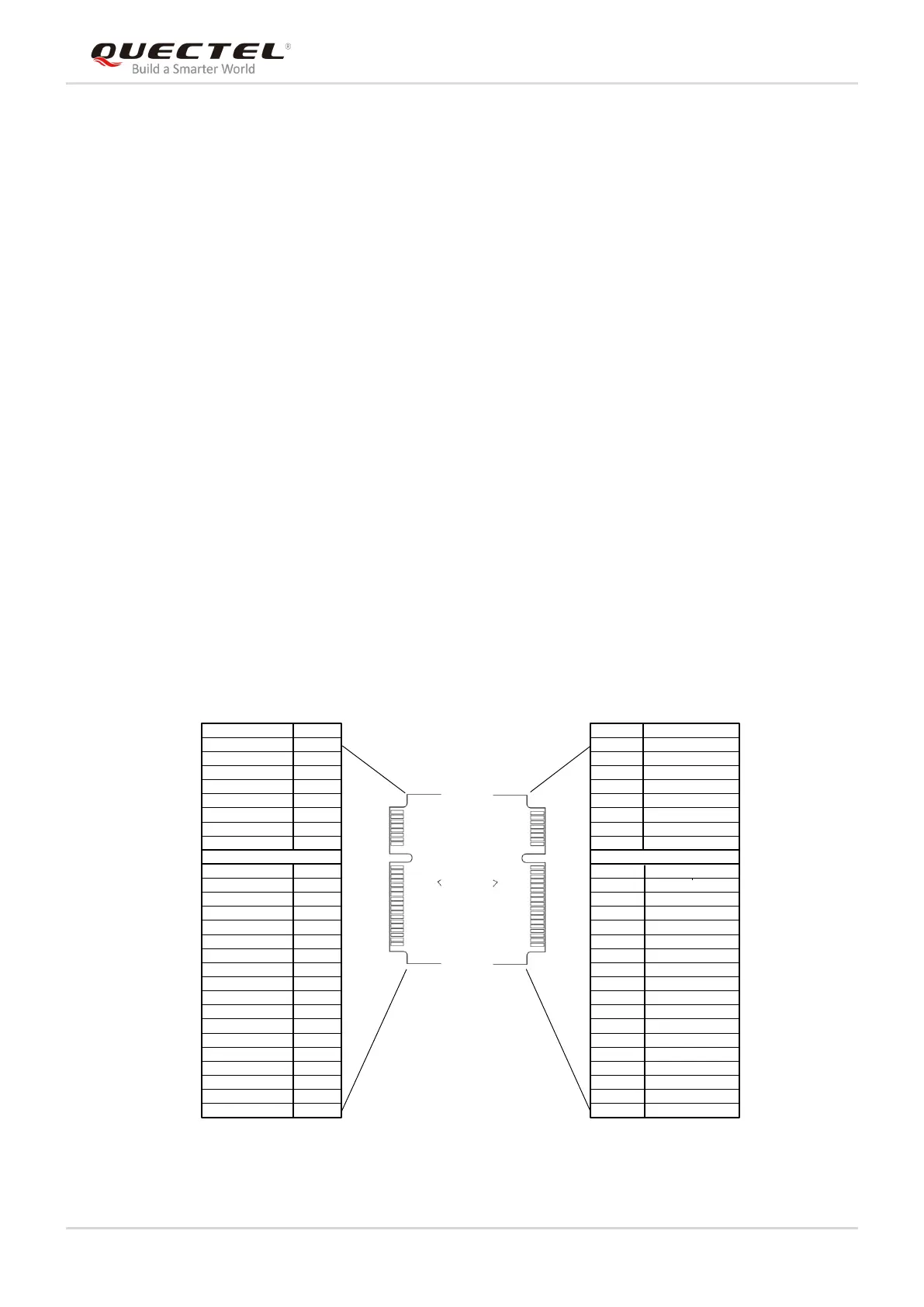
3.1. Pin Assignment
The following figure shows the pin assignment of EG21-G Mini PCIe module. The top side contains
EG21-G module and antenna connectors.
PIN2
PIN52
BOT
PIN1
PIN51
TOP
Pin Name
Pin No.
WAKE#
1
3
5
7
9
11
13
15
17
19
21
23
25
27
29
31
33
35
37
39
41
43
45
47
49
51
RESERVED
RESERVED
RESERVED
GND
UART_RX
UART_TX
GND
RI
RESERVED
GND
UART_CTS
UART_RTS
GND
GND
DTR
RESERVED
GND
GND
VCC_3V3
VCC_3V3
GND
PCM_CLK
PCM_DOUT
PCM_DIN
PCM_SYNC
Pin Name
Pin No.
2
4
6
8
10
12
14
16
18
20
22
24
26
28
30
32
34
36
38
40
42
44
46
48
50
52
VCC_3V3
GND
NC
USIM_VDD
USIM_DATA
USIM_CLK
USIM_RST
RESERVED
GND
W_DISABLE#
PERST#
RESERVED
GND
NC
I2C_SCL
I2C_SDA
GND
USB_DM
USB_DP
GND
LED_WWAN#
USIM_PRESENCE
RESERVED
NC
GND
VCC_3V3
Figure 2: Pin Assignment

Other manuals for Quectel LTE Standard Module Series

Related product manuals