LTE Standard Module Series
EG21-G Mini PCIe Hardware Design
EG21-G_Mini_PCIe_Hardware_Design 27 / 54
3.8. Control and Indication Signals
The following table shows the pin definition of control and indication signals.
Table 11: Pin Definition of Control and Indication Signals
3.8.1. RI Signal
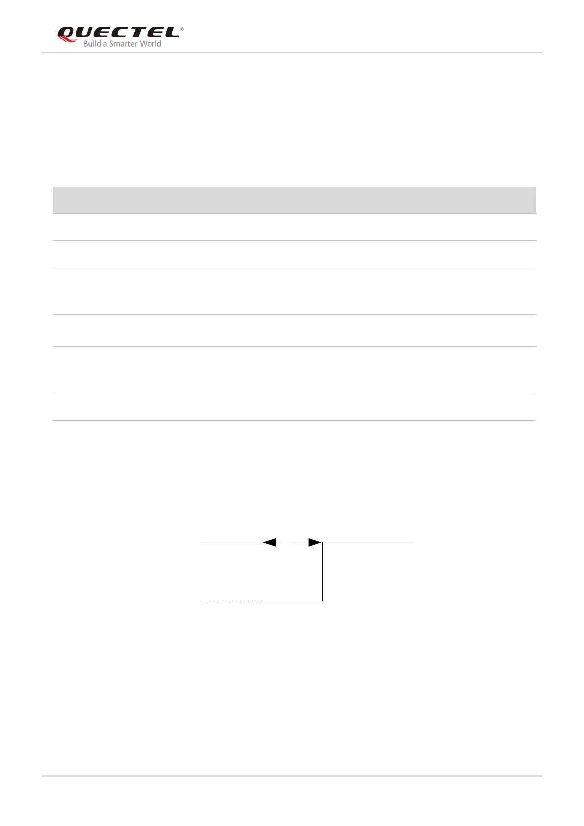
The RI signal can be used to wake up the host. When a URC returns, there will be the following behaviors
on the RI pin after executing AT+QCFG="risignaltype","physical" command.
Figure 11: RI Behaviors
3.8.2. DTR Signal
The DTR signal is used for sleep mode control. It is pulled up by default. When module is in sleep mode,
driving it to low can wake up the module. For more details about the preconditions for module to enter
sleep mode, please refer to Chapter 3.4.1.