EasyManua.ls Logo

Quectel LTE Standard Module Series - U)SIM Interface

Quectel LTE Standard Module Series
55 pages
To Next Page IconTo Next Page
To Previous Page IconTo Previous Page
Loading...
LTE Standard Module Series
EG21-G Mini PCIe Hardware Design
EG21-G_Mini_PCIe_Hardware_Design 20 / 54
LDO_IN
C1
C2
MIC29302WU U1
IN
OUT
EN
GND
ADJ
2 4
1
3
5
VCC_3V3
100nF
C3
470uF
C4
100nF
R2
82K 1%
47K 1%
R3
470uF
470R
51K
R4
R1
MCU_POWER
_ON/OFF
47K
4.7K
R5
R6
C5
C6
33pF
10pF
TVS
D1
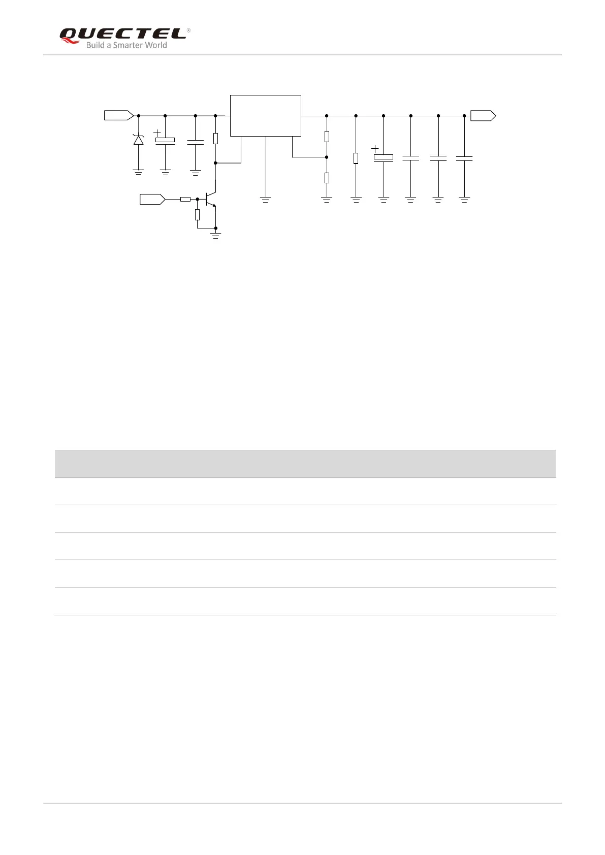
Figure 3: Reference Circuit of Power Supply
3.4. (U)SIM Interface
The (U)SIM interface circuitry meets ETSI and IMT-2000 requirements. Both 1.8V and 3.0V (U)SIM cards
are supported. The following table shows the pin definition of (U)SIM interface.
Table 7: Pin Definition of (U)SIM Interface
EG21-G Mini PCIe supports (U)SIM card hot-plug via the USIM_PRESENCE pin. The function supports
low level and high level detections. By default, It is disabled, and can be configured via AT+QSIMDET
command. Please refer to document [2] for details about the command.
The following figure shows a reference design for (U)SIM interface with an 8-pin (U)SIM card connector.
Pin Name
Pin No.
I/O
Power Domain
Description
USIM_VDD
8
PO
1.8V/3.0V
Power supply for (U)SIM card
USIM_DATA
10
IO
1.8V/3.0V
Data signal of (U)SIM card
USIM_CLK
12
DO
1.8V/3.0V
Clock signal of (U)SIM card
USIM_RST
14
DO
1.8V/3.0V
Reset signal of (U)SIM card
USIM_PRESENCE
44
DI
1.8V
(U)SIM card insertion detection

Other manuals for Quectel LTE Standard Module Series

Related product manuals