LTE Standard Module Series
EG21-G Mini PCIe Hardware Design
EG21-G_Mini_PCIe_Hardware_Design 24 / 54
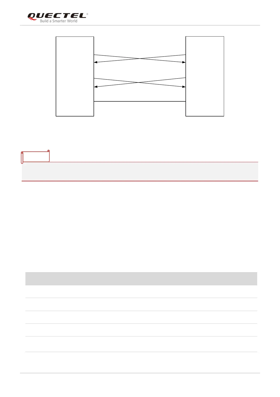
MCU/ARM
TXD
RXD
UART_RXD
UART_TXD
UART_RTS
UART_CTS
RTS
CTS
GND
Module
GND
Voltage level: 3.3V
Voltage level: 3.3V
Figure 7: Reference Circuit of Power Supply
AT+IPR can be used to set the baud rate of the main UART, and AT+IFC can be used to set the hardware
flow control (hardware flow control is disabled by default). Please refer to document [2] for details.
3.7. PCM and I2C Interfaces
EG21-G Mini PCIe provides one Pulse Code Modulation (PCM) digital interface and one I2C interface.
The following table shows the pin definition of PCM and I2C interfaces that can be applied in audio codec
design.
Table 10: Pin Definition of PCM and I2C Interfaces
PCM frame synchronization
I2C serial clock.
Require external pull-up to 1.8V.