EasyManua.ls Logo

Quectel M35 - Table 7: Logic Levels of the Uart Interfaces

Quectel M35
86 pages
To Next Page IconTo Next Page
To Previous Page IconTo Previous Page
Loading...
GSM/GPRS Module Series
M35 User Manual
M35_User_Manual Confidential / Released 38 / 85
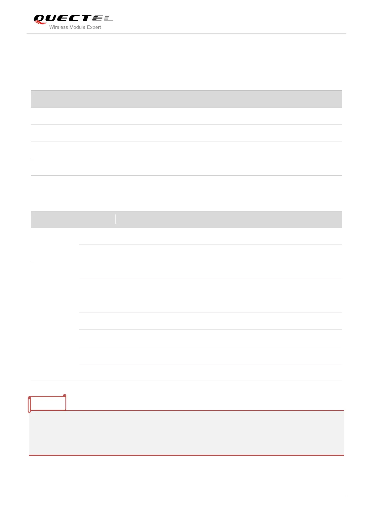
The logic levels are described in the following table.
Table 7: Logic Levels of the UART Interfaces
Table 8: Pin Definition of the UART Interfaces
1.
1)
DTR pin can be used as SIM1_PRESENCE pin via AT+QSIMDET command.
2.
2)
When using the SIM2 interface, DCD pin can be used as SIM2_RST pin. For more details, please
refer to the document [6].
3.
3)
When using the PCM interface, RI pin can be used as PCM_CLK.
Parameter
Min.
Max.
Unit
V
IL
0
0.25×VDD_EXT
V
V
IH
0.75×VDD_EXT
VDD_EXT +0.2
V
V
OL
0
0.15×VDD_EXT
V
V
OH
0.85×VDD_EXT
VDD_EXT
V
Interfaces
Pin No.
Pin Name
Description
Alternate Function
Debug Port
14
DBG_RXD
Receive data
15
DBG_TXD
Transmit data
UART Port
20
1)
DTR
Data terminal ready
SIM1_PRESENCE
21
RXD
Receive data
22
TXD
Transmit data
23
CTS
Clear to send
24
RTS
Request to send
25
2)
DCD
Data carrier detection
SIM2_RST
26
3)
RI
Ring indication
PCM_CLK
NOTE

Table of Contents

Related product manuals