EasyManua.ls Logo

Quectel MC60 Series User Manual

Quectel MC60 Series
115 pages
To Next Page IconTo Next Page
To Previous Page IconTo Previous Page
Page #41 background imageLoading...
Page #41 background image
GSM/GPRS/GNSS Module Series
MC60 Series Hardware Design
MC60_Series_Hardware_Design Confidential / Released 40 / 114
In periodic standby mode, sending ―$PMTK225,0*2B‖ in any time can make the module enter into full on
mode.
In periodic backup mode, sending ―$PMTK225,0*2B‖ during the Run_time or 2nd_run_time period can
also make the module enter into full on mode. But this is hard to operate and thus is not recommended.
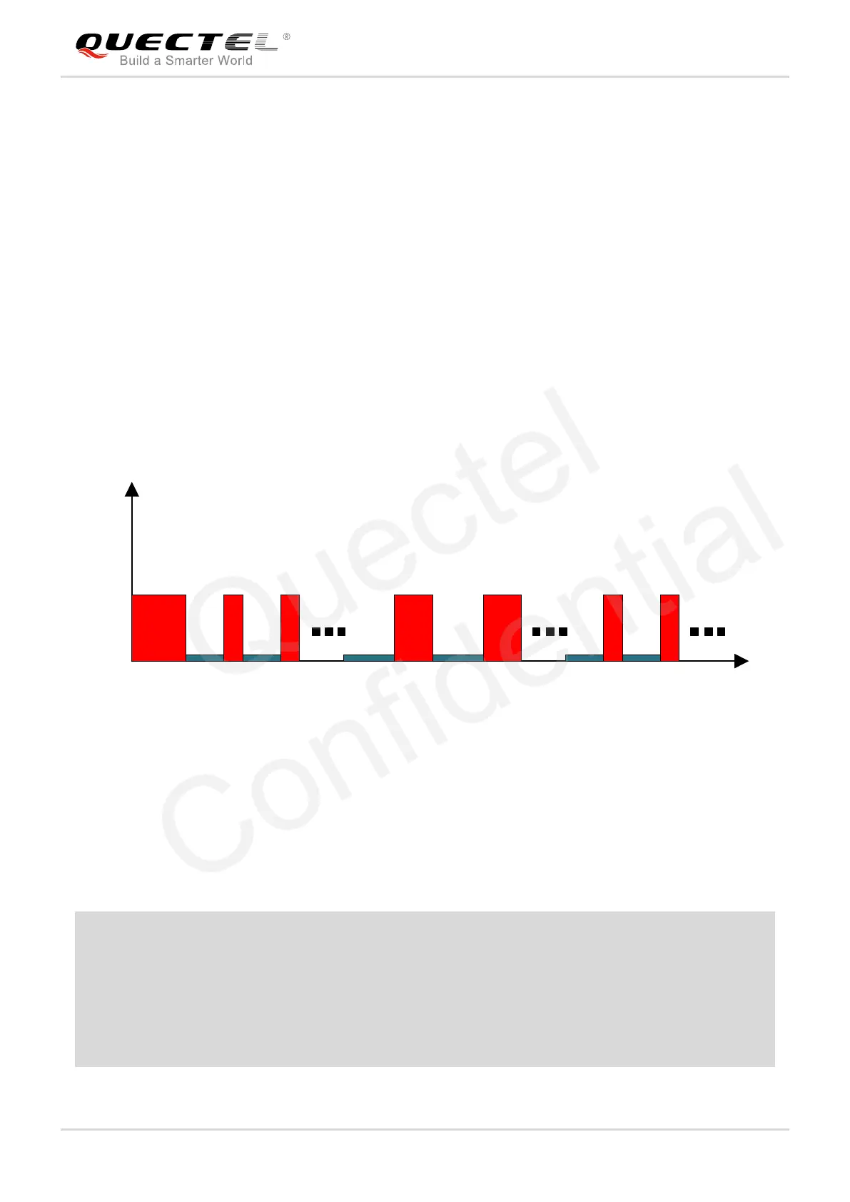
The following figure has shown the operation mechanism of periodic mode. When customers send PMTK
command, the module will be in full on mode first. Several minutes later, the module will enter into
periodic mode according to the parameters set. When the module fails to fix the position during Run_time,
the module will switch to 2nd_run_time and 2nd_sleep_time automatically. As long as the module fixes
the position again successfully, the module will return to Run_time and Sleep_time.
Before entering into periodic mode, please make sure the module is in tracking mode; otherwise the
module may have a risk of failure in satellite tracking. If module is located in weak signal areas, it is better
to set a longer 2nd_run_time to ensure the success of reacquisition.
Power
Run time
Run time
Sleep time
Sleep time
Second run timeSecond run time
Second sleep time Second sleep time
Run time
Run time
Sleep time
Sleep time
Full on
Figure 14: Operation Mechanism of Periodic Mode
The average current consumption in periodic mode can be calculated based on the following formula:
I
periodic
= (I
tracking
*T1+I
standby/backup
*T2)/(T1+T2) T1: Run_time, T2: Sleep_time
Example
PMTK225,2,3000,12000,18000,72000*15 for periodic mode means 3s in tracking mode and 12s in
standby mode based on GPS&GLONASS. The average current consumption is calculated below:
I
periodic
= (I
tracking
*T1+I
standby
*T2)/(T1+T2) = (22mA*3s+0.5mA*12s)/(3s+12s) 4.8(mA)
PMTK225,1,3000,12000,18000,72000*15 for periodic mode means 3s in tracking mode and 12s in
backup mode based on GPS&GLONASS. The average current consumption is calculated below:
I
periodic
= (I
tracking
*T1+I
backup
*T2)/(T1+T2) = (22mA*3s+0.007mA*12s)/(3s+12s) 4.4(mA)
Quectel
Confidential

Table of Contents

Question and Answer IconNeed help?

Do you have a question about the Quectel MC60 Series and is the answer not in the manual?

Quectel MC60 Series Specifications

General IconGeneral
Form FactorLCC
Operating Temperature-40°C to +85°C
Storage Temperature-45°C to +90°C
GNSSGPS/GLONASS/BeiDou/Galileo/QZSS
Power Supply Voltage3.3V to 4.3V
InterfaceUART, SPI, I2C, ADC, GPIO
SIM Card1.8V/3V
Network StandardsGSM/GPRS
L1 Band1575.42MHz
Acquisition Time<1s
Accuracy<2.5m CEP
Frequency BandsGSM 850/900/1800/1900MHz
CertificationsCE/GCF/NCC/PTCRB
Firmware UpdateVia UART

Summary

Introduction

Safety Information

Safety precautions for operating, servicing, or repairing the MC60 module.

Product Concept

General Description and Key Features

Overview of MC60 module, its features, and applications.

Functional Diagram and Evaluation Board

Block diagram of MC60's functional parts and evaluation board.

Application Functions

Pin Definitions and Assignment

Detailed description of MC60 module pins, their assignment, and I/O parameters.

Power Supply

Power Features and Voltage Drop

Power supply requirements, features, and methods to decrease voltage drop.

Operating Modes

GSM and GNSS Operating Modes

Overview of operating modes for both GSM and GNSS parts of the MC60 module.

Power Management Scenarios

All-in-one Solution Power Control

Procedures for powering on/off the module in All-in-one mode.

Stand-alone Solution Power Control

Procedures for powering on/off the GSM part in Stand-alone mode.

Serial Interfaces

UART Port and Connections

Details on UART port, its features, connections, and firmware upgrade.

Audio Interfaces

Audio Interface Designs

Reference designs for microphone, receiver, speaker, and earphone interfaces.

PCM Interface

PCM Configuration and Timing

PCM interface parameters, configuration, and timing diagrams.

(U)SIM and SD Card Interfaces

(U)SIM Card Interface Details

Pin definition and reference circuits for (U)SIM card interface.

SD Card Interface Details

Features and reference design for the SD card interface.

Network Status & AGPS

Network Status Indication

Working states of the NETLIGHT signal for network status.

EASY Autonomous AGPS Technology

Technology to improve TTFF and acquisition sensitivity using AGPS.

Antenna Interfaces

GSM, GNSS, and Bluetooth Antenna Details

Interface requirements and reference designs for GSM, GNSS, and BT antennas.

Electrical & Mechanical Characteristics

Electrical Ratings and Temperature

Absolute maximum ratings, operating temperature, and current consumption.

Mechanical Dimensions and Footprint

Module dimensions, recommended footprint, and views.

Storage, Manufacturing, and Packaging

Manufacturing and Soldering Guidelines

Guidelines for manufacturing, soldering, and packaging the module.

Appendices

References and GPRS Information

List of related documents and GPRS coding schemes.

Related product manuals