EasyManua.ls Logo

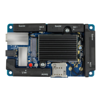
Quectel RMU500-EK - EVB Component Layout; Component Placement of the EVB

Quectel RMU500-EK
29 pages
To Next Page IconTo Next Page
To Previous Page IconTo Previous Page
Loading...
5G Module Series
RMU500-EK User Guide
RMU500-EK_User_Guide 10 / 28
2.2. Component Placement of the EVB
Shielding Cover
J301
J101
Shielding
Cover
J401
Type-B
D104 D107
Figure 1: Component Placement of the EVB (Top View)
Table 2: Interfaces and Functions of the EVB
Interfaces
Reference Designators
Description
Power Supply
J101 (Power Jack)
The power jack on the EVB
Typical supply voltage: +5 V/ 2.5 A
J301 (Type-C USB)
Type-C USB interface
Typical supply voltage: +5 V/ 2 A
M.2 Interface
J201
The M.2 connecter for the module
USB Interface
J301
USB interface
(U)SIM Interface
J401
(U)SIM card connector
Indicator LEDs
D104 (POWER_LED)
Power indicator, indicating whether the modules power
supply is ready.
D107 (WWAN_LED)
RF status indicator
DDd
D10
4

Related product manuals