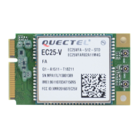
Do you have a question about the Quectel RM500Q-AE and is the answer not in the manual?
Essential safety precautions for operating and maintaining the module.
Overview of the module's capabilities and supported networks.
Detailed list of the module's technical specifications and functionalities.
Block diagram illustrating the module's internal architecture and components.
Information on Quectel's evaluation board for application development.
Visual representation of module pins and their assignments.
Detailed explanation of each module pin's function and characteristics.
Summary of the module's different operating states and their characteristics.
Defines VCC and GND pin requirements and power supply considerations.
Guidance on managing voltage drop for stable power supply.
Provides a reference schematic for a power supply circuit.
Explains the procedures for powering the module on and off.
Details on how to initiate the module's power-on sequence.
Describes methods for safely shutting down the module.
Specifies the (U)SIM card interface requirements and pin definitions.
Details the USB interface, including specifications and pin definitions.
Covers the PCIe interface, its compliance, and pin definitions.
Explains the communication modes available via USB and PCIe interfaces.
Describes the Pulse Code Modulation interface for audio communication.
Defines pins used for module control and status indication.
Control pin for airplane mode and RF function status.
Control pin for GNSS function status.
Pin for indicating WWAN RF status via an LED.
Wake-up signal pin to alert the host.
Dynamic Power Reduction pin for body SAR detection.
Status indication pins for communication with host devices.
Defines the Coexistence (COEX) interface for Cellular/WLAN.
Interface for controlling external antenna tuners.
Pins used for configuring module operation and type.
Overview of the integrated GNSS solution and supported systems.
Specifications for GNSS sensitivity, TTFF, and accuracy.
Details on RF antenna ports, including pin definitions.
Maps pins to specific antenna interfaces and their functions.
Shows how different bands map to antenna connectors.
Lists the operating frequencies for various cellular bands.
Provides a reference circuit for RF antenna connections.
Specifies the frequency range for the GNSS antenna connector.
Guidelines for designing RF traces and layout on the PCB.
Illustrates the physical antenna connectors used on the module.
Lists RF bands supported by each antenna connector.
Requirements and recommendations for installing antennas.
Specifies requirements for WCDMA, LTE, 5G NR, and GNSS antennas.
Details the RF connector type and its mating plug specifications.
Specifies the limits for voltage and power supply parameters.
Outlines the voltage, ripple, and drop requirements for the power supply.
Defines the voltage levels for digital input and output signals.
Specifies the temperature ranges for module operation and storage.
Provides typical current consumption values under various operating conditions.
Lists the RF output power for different WCDMA, LTE, and 5G NR bands.
Details the conducted RF receiving sensitivity across various bands.
Electrostatic discharge characteristics for different interfaces.
Recommendations for thermal management and dissipation.
Provides the physical dimensions and tolerances of the module.
Visual representation of the module's top and bottom surfaces.
Information on the standard PCI Express M.2 connector used.
Describes the tray packaging procedures and quantities.
Lists the FCC rules applicable to the module.
Refers to FCC certification requirements for RF exposure.
Details antenna specifications including frequency range and peak gain.
Details limitations for OEM installation and antenna gain.
Instructions for labeling the host product with FCC ID and module information.
Statements regarding compliance with FCC rules, interference, and modifications.
| Form Factor | M.2 |
|---|---|
| Operating Temperature | -40°C to +85°C |
| 5G NR Sub-6 GHz | Yes |
| LTE Category | Cat 20 |
| LTE DL | Up to 2 Gbps |
| Module Type | 5G Module |
| Category | 5G |
| Technology | 5G NR, LTE |
| Weight | Approx. 10g |
| Power Supply | 3.3V |
| Interface | PCIe, USB 3.0, UART |
| SIM Interface | 1.8V/3.0V |
| GNSS | GPS, GLONASS, BeiDou, Galileo |
| Certifications | FCC/IC/CE |


