EasyManua.ls Logo

Quectel RM500Q-AE - WWAN_LED#*

Quectel RM500Q-AE
87 pages
To Next Page IconTo Next Page
To Previous Page IconTo Previous Page
Loading...
5G Module Series
RM500Q-AE&RM502Q-AE Hardware Design
RM500Q-AE&RM502Q-AE_Hardware_Design 47 / 83
Host Module
W_DISABLE2#
W_DISABLE1#
BB
GPIO
GPIO
26
8
VDD 1.8 V
Note: The voltage level of VCC_IO_HOST could be 1.8 V or 3.3 V typically.
R3
100k
R2
100k
R5
10k
VCC_IO_HOST
R6
10k
Figure 22: W_DISABLE1# and W_DISABLE2# Reference Circuit
3.9.3. Figure 26: W_DISABLE1# and W_DISABLE2# Reference Circuit
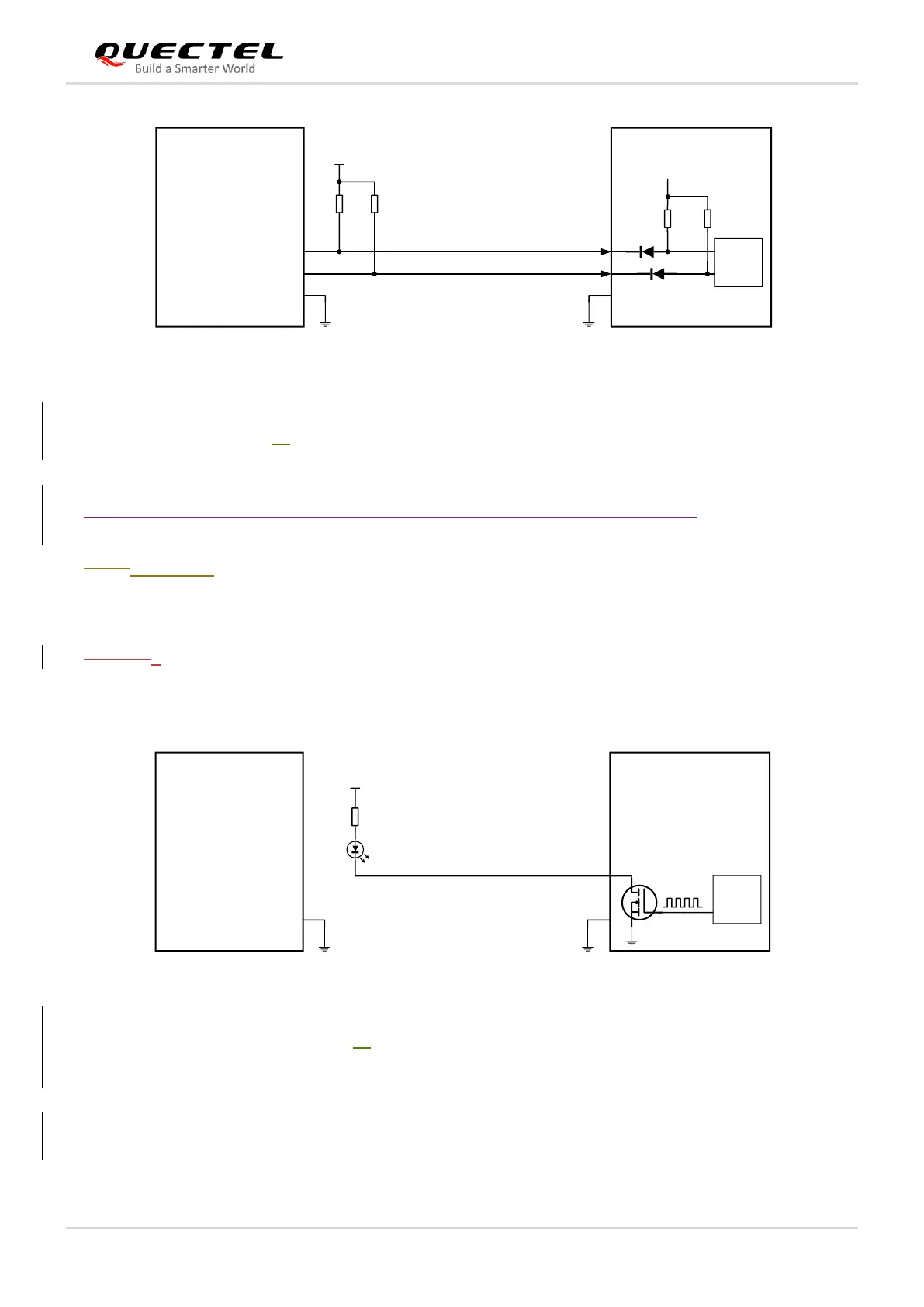
3.9.4.3.11.3. WWAN_LED#*
The WWAN_LED# signal is used to indicate RF status of the module, and its sink current is up to 10 mA.
In order tTo reduce current consumption of the LED, a current-limited resistor must be placed in series
with the LED, as illustrated in the figure below. The LED is ON when the WWAN_LED# signal is at low
level.
Host Module
WWAN_LED#
PMU
GPIO
10
VCC
Note: This VCC could be the power supply of the module.
LED
R1
330Ω
Figure 23: WWAN_LED# Reference Circuit
The following table shows the RF status indicated by WWAN_LED# .

Table of Contents

Related product manuals