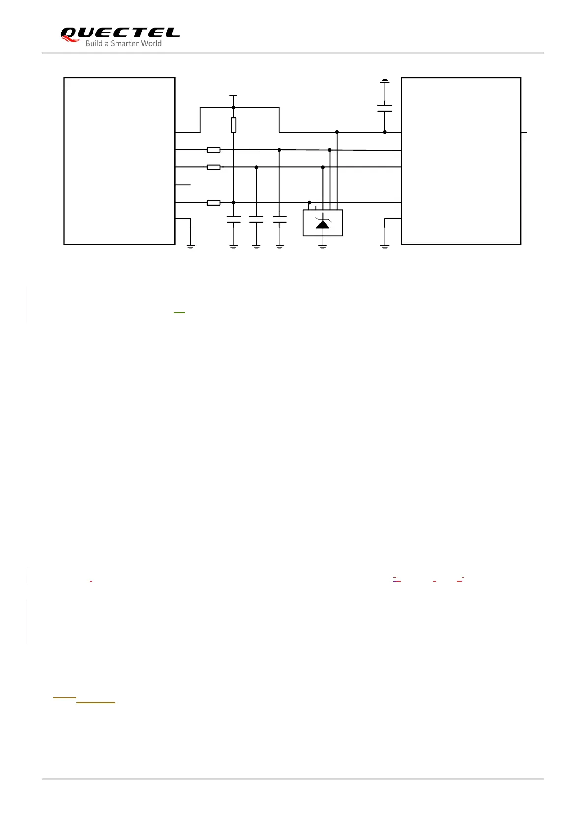
Figure 15: Reference Circuit for a 6-Pin (U)SIM Card Connector
To enhance the reliability and availability of the (U)SIM card in applications, please follow the criteria
below in (U)SIM circuit design.
⚫ Place the (U)SIM card connector as close to the module as possible. Keep the trace length less than
200 mm.
⚫ Keep (U)SIM card signals away from RF and VCC traces.
⚫ Make sure the ground between the module and the (U)SIM card connector is short and wide. Keep
the trace width of ground and USIM_VDD no less than 0.5 mm to maintain the same electric
potential.
⚫ To avoid cross-talk between USIM_DATA and USIM_CLK, keep them away from each other and
shield them with surrounded ground.
⚫ To offer better ESD protection, add a TVS diode array of which the parasitic capacitance should be
not higher than 10 pF. Add 22 Ω resistors in series between the module and the (U)SIM card
connector to suppress EMI such as spurious transmission, and to enhance ESD protection. The 33
pF capacitors are used to filter out RF interference.
⚫ For USIM_DATA, a 10–20 kΩ pull-up resistor must be added near the (U)SIM card connector.
⚫ (U)SIM card hot-plug is disabled by default.
3.6.3.8. USB Interface
RM500Q-AE&RM502Q-AE module provides one integrated Universal Serial Bus (USB) interface which
complies with the USB 3.1 & 2.0 specifications and supports super speed (10) on USB 3.1 and high