5G Module Series
RM500Q-AE&RM502Q-AE Hardware Design
RM500Q-AE&RM502Q-AE_Hardware_Design 29 / 83
3.4.3.5. Turn on and off Scenarios
3.4.1.3.5.1. Turn on the Module
FULL_CARD_POWER_OFF# asynchronous signal is an Active Low input that is used to turn off the
entire module. When the input signal is asserted high ( ≥ 1.19 V), the module will be enabled. When the
input signal is driven low signal ( ≤ 0.2 V) or Tri-stated, it will force the module to shut down.
This input signal is 3.3 V tolerant and can be driven by either 1.8 V or 3.3 V GPIO. Also, it has internally
pulled down with a 100 kΩ resistor.
The following table shows the definition of FULL_CARD_POWER_OFF#.
Table 776: Definition of FULL_CARD_POWER_OFF# Pin
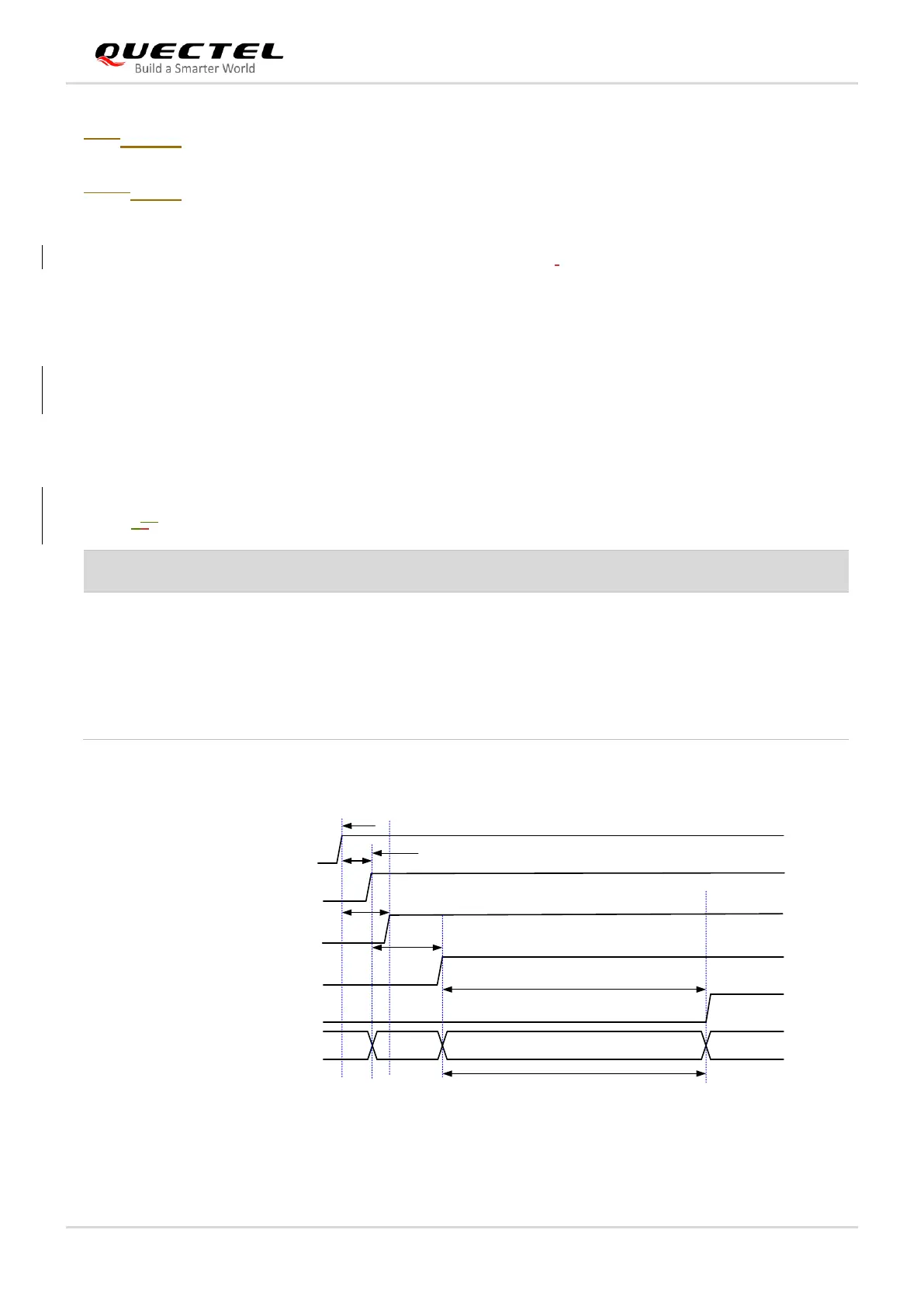
The timing of turn-on scenario is illustrated in the following figure.
Internally pulled down with a
100 kΩ resistor
When it is at low level, the
module is powered off.
When it is at high level, the
module is powered on.