5G Module Series
RM500Q-AE&RM502Q-AE Hardware Design
RM500Q-AE&RM502Q-AE_Hardware_Design 45 / 83
3.9.3.11. Control and Indication Interfaces
The following table shows the pin definition of control and indication pins.
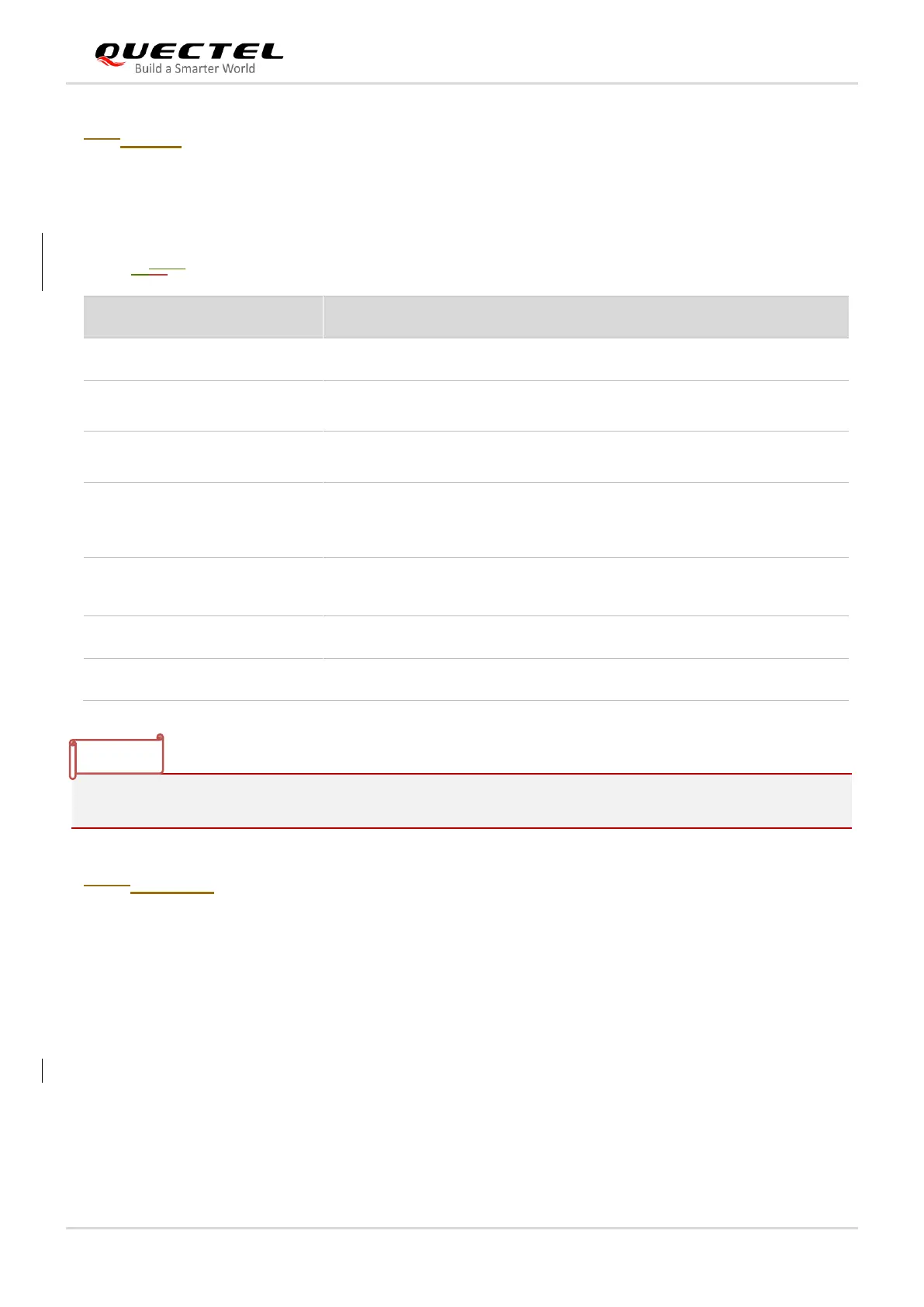
Table 131312: Pin Definition of Control and Indication Interfaces
“*” means under development.
3.9.1.3.11.1. W_DISABLE1#*
The module provides a W_DISABLE1# pin to disable or enable airplane mode through hardware
operation. The W_DISABLE1# pin is pulled up by default. Driving it low will set the module to airplane
mode. In airplane mode, the RF function will be disabled.
The RF function can also be enabled or disabled through software AT commands. The following table
shows the RF function status of the module.
Airplane mode control. Active LOW.
Indicate RF status of the module.
Open drain and
active low signal.
Open drain and
active low signal.
1.8 V power domain.
High voltage level by
default.
1.8/3.3 V power
domain.
Active LOW.
Status indication from AP