5G Module Series
RM500Q-AE&RM502Q-AE Hardware Design
RM500Q-AE&RM502Q-AE_Hardware_Design 35 / 83
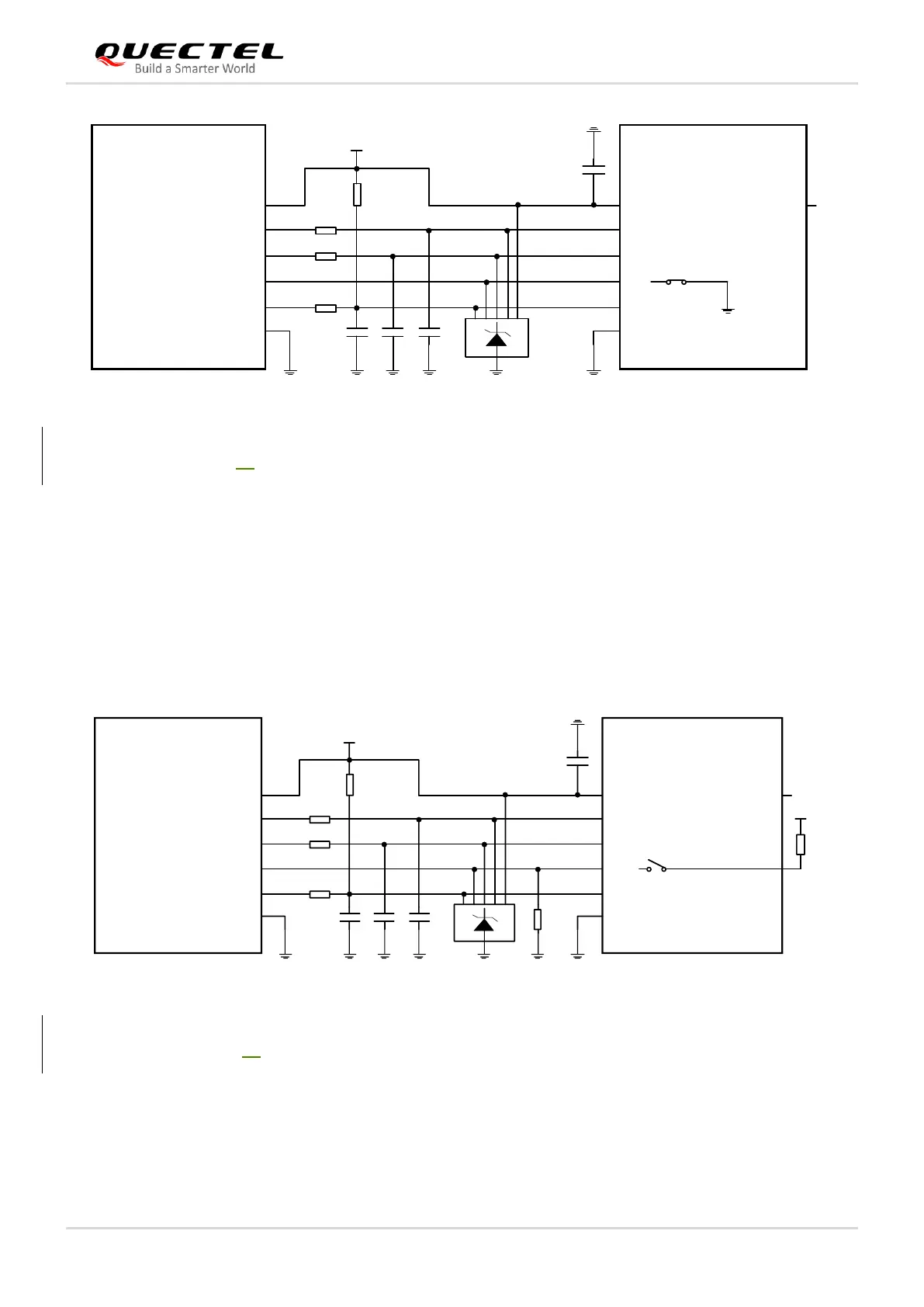
Module (U)SIM Card
Connector
USIM_DET
USIM_DATA
USIM_CLK
RST
CLK
CD
IO
USIM_VDD
USIM_VDD
USIM_RST
VCC
GND
VPP
GND
TVS
Note: All these resistors, capacitors and TVS should be close to (U)SIM card connector in PCB layout.
10-20k
22R
22R
22R
33 pF
33 pF
33 pF
100 nF
Figure 13: Reference Circuit for Normally Closed (U)SIM Card Connector
Normally Open (U)SIM Card Connector:
⚫ When the (U)SIM is absent, CD1 is open from CD2 and USIM_DET is at low voltage level.
⚫ When the (U)SIM is inserted, CD1 is short-circuited to 1.8 V and USIM_DET is at high voltage level.
The following figure shows a reference design of (U)SIM interface with a normally open (NO) (U)SIM card
connector.
Module (U)SIM Card
Connector
USIM_DET
USIM_DATA
USIM_CLK
RST
CLK
CD1
IO
USIM_VDD
USIM_VDD
USIM_RST
VCC
GND
VPP
GND
TVS
Note: All these resistors, capacitors and TVS should be close to (U)SIM card connector in PCB layout.
10-20k
22R
22R
22R
33 pF
33 pF
33 pF
100 nF
33k
1.8 V
4.7k
CD2
Figure 14: Reference Circuit for Normally Open (U)SIM Card Connector
If (U)SIM card detection function is not needed, please keep USIM_DET disconnected. A reference circuit
for (U)SIM card interface with a 6-pin (U)SIM card connector is illustrated by the following figure.