EasyManuals Logo

Quectel SG368Z-AP User Manual

Quectel SG368Z-AP
117 pages
To Next Page IconTo Next Page
To Previous Page IconTo Previous Page
Page #58 background imageLoading...
Page #58 background image
Smart Module Series
SG368Z_Series_Hardware_Design 57 / 113
VDDIN
VDDIN
VDDIN
GND
PWM
GND
EDP_ML0_P
NC
NC
NC
BL_EN
HPD
GND
DAUXP
DRX0P
DRX0N
GND
GND
GND
1
2
3
4
5
6
7
8
9
10
12
13
14
15
16
17
18
19
20
21
22
23
24
25
26
27
GND
VLED
29
28
30
11
100 nF
4.7 μF
Module
eDP LCD
C1
NC
NC
NC
GND
EDP_ML0_N
EDP_ML1_P
EDP_ML1_N
EDP_ML2_P
EDP_ML2_N
EDP_ML3_P
EDP_ML3_N
EDP_AUX_P
EDP_AUX_N DAUXN
DRX1P
DRX1N
DRX2P
DRX2N
DRX3P
DRX3N
C2
VCC_3V3
Level shift
Level shift
Level shift
VCC_12V
100 nF
4.7 μF
C3 C4
100 nFC5
100 nFC6
100 nFC7
100 nFC8
100 nFC9
100 nFC10
100 nFC11
100 nFC12
100 nFC13
100 nFC14
R1
100K
R2
100K
GPIO
PWM
EDP_DET
Figure 17: Reference Design of eDP Interface
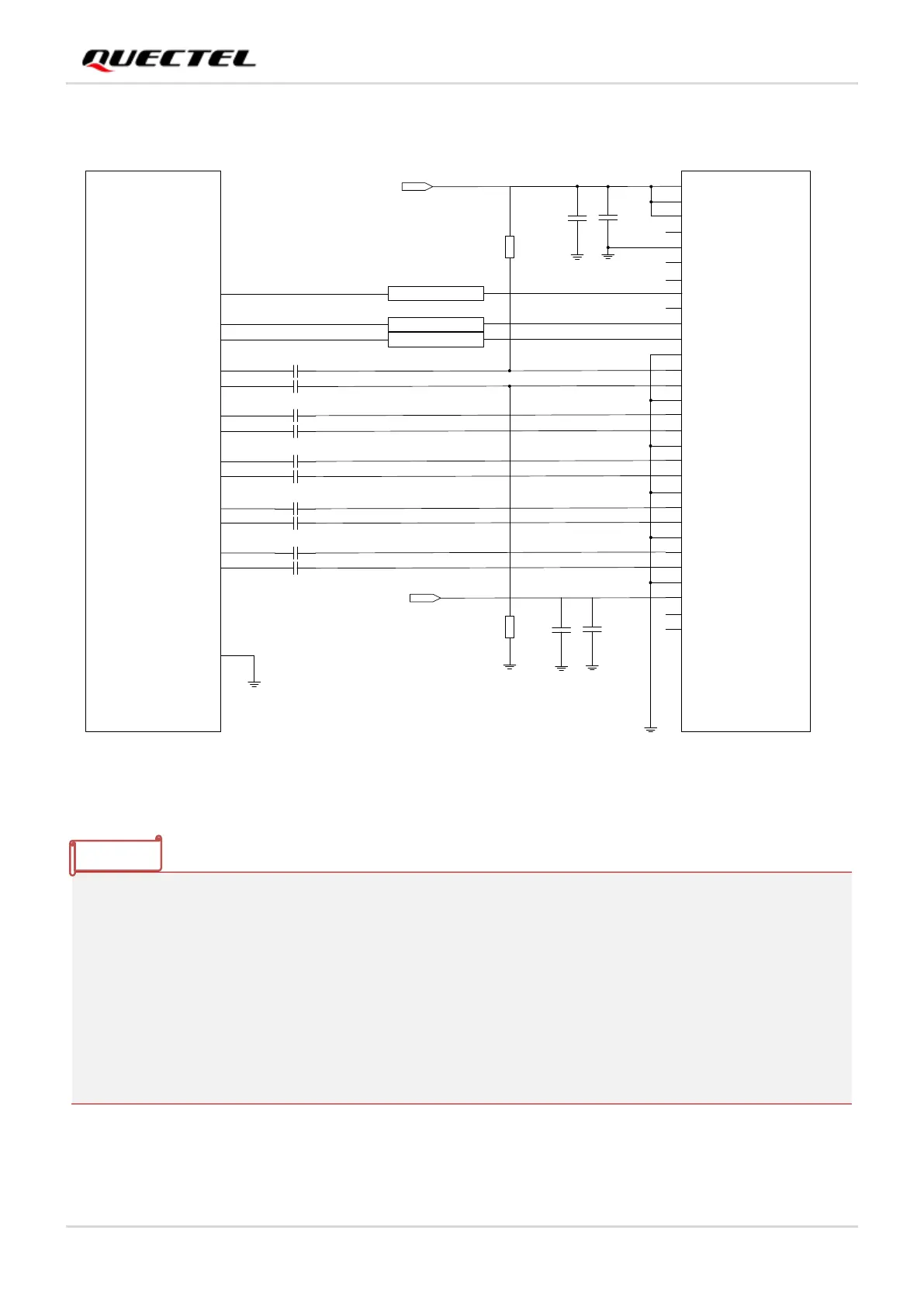
1. Confirm that whether level-shift is needed for PWM, BL_EN, HPD and other signals according to the
selected module pins and eDP LCD specifications.
2. For LCDs that support eDP V1.2a and above protocols, R1 and R2 are not mounted.
3. If the eDP LCD has requirements on the power-up timing, the modules GPIO can be selected for
timing control.
4. If the application scenario involves frequent plugging and unplugging of the eDP connector or has
high requirements for ESD protection, it is recommended to reserve a TVS near the connector, and
the TVS junction capacitance should not exceed 0.4 pF.
5. EDP_DET is optional and can be configured as required.
NOTE

Table of Contents

Questions and Answers:

Question and Answer IconNeed help?

Do you have a question about the Quectel SG368Z-AP and is the answer not in the manual?

Quectel SG368Z-AP Specifications

General IconGeneral
BrandQuectel
ModelSG368Z-AP
CategoryControl Unit
LanguageEnglish

Related product manuals