Do you have a question about the Quectel SC206E Series and is the answer not in the manual?
Confidentiality and usage terms for provided documents and information.
Protection of Quectel and third-party intellectual property.
Rules for using Quectel or third-party trademarks.
Data processing and privacy considerations for module functionality.
Limitation of liability for document information and product features.
General information about the document's purpose and scope.
Records changes and updates made to the document over time.
Details on compliance with FCC regulations for the module.
Industry Canada compliance statements and labeling requirements.
Explanation of special marks used in the document for status indication.
Details on supported frequency bands and core functionalities of the SC206E series.
Highlights the main technical specifications and capabilities of the SC206E module.
Visual representation of the module's internal architecture and major functional blocks.
Information on the Evaluation Board for application development and testing.
Overview of the various interfaces and functions supported by the SC206E series modules.
Diagram showing the physical pin layout and numbering of the module.
Details of module pins, including power, audio, USB, SIM, SD, and more.
Description of pins related to audio input and output, including microphones and speakers.
Detailed pinout for USB 3.1 and USB 2.0 interfaces, including Type-C.
Definition of pins for the three UART interfaces (UART0, UART1, UART4).
Pin definitions for two (U)SIM interfaces, supporting dual SIM and various voltage levels.
Pin definitions for the SD card interface supporting SD 3.0 protocol.
Pin definitions for the I2C interface connecting to a Touch Panel (TP).
Pin definitions for the MIPI DSI compliant Liquid Crystal Module (LCM) interface.
Pin definitions for camera interfaces supporting MIPI CSI, including multiple lanes and cameras.
Definition for the flash LED driver pin supporting flash and torch modes.
Pin for indicating the module's charging status.
Pins for keypad control, including power key and volume buttons.
Definition of pins for the three UART interfaces (UART0, UART1, UART4).
I2C interface pins for external sensors.
Pins for main, GNSS, and Wi-Fi/Bluetooth antennas.
Pins for controlling antenna tuner functions.
Definition for the single Analog-to-Digital Converter (ADC) interface.
Pins related to battery voltage and temperature detection for charging.
Pin for controlling the vibration motor driver.
Miscellaneous interface pins like USB_BOOT and GNSS_LNA_EN.
General Purpose Input/Output pins.
Details on power supply pins and voltage stability requirements.
Schematic for a +5V input power supply reference circuit, with typical output voltage and current.
Methods for turning the module on and off using the PWRKEY pin.
Details on the Real Time Clock power supply using an external source like a coin cell.
Description of regulated voltage outputs for peripheral circuits and recommended filtering.
Information about the module's battery charging capabilities and modes (trickle, CC, CV).
Detailed pinout for USB 3.1 and USB 2.0 interfaces, including Type-C.
Pin definitions for the three UART interfaces (UART0, UART1, UART4), including reference circuit.
Pin definitions for two (U)SIM interfaces, supporting dual SIM and various voltage levels.
Pin definitions for the SD card interface supporting SD 3.0 protocol.
Definitions for numerous General Purpose Input/Output (GPIO) pins.
Pin definitions for the four I2C interfaces used for sensors and camera control.
Definition for the single Analog-to-Digital Converter (ADC) interface.
Definition for the pin controlling the vibration motor driver.
Pin definitions for the MIPI DSI compliant Liquid Crystal Module (LCM) interface.
Pin definitions for camera interfaces supporting MIPI CSI, including multiple lanes and cameras.
Pin definitions for analog audio input and output channels.
Guidelines for routing MIPI high-speed signal lines for optimal performance and reliability.
Definition of the USB_BOOT pin used for emergency download mode.
Details on Wi-Fi capabilities, standards, and features supported by the module.
Table showing Wi-Fi transmitting and receiving performance metrics.
Table detailing Bluetooth transmitting and receiving performance.
Performance metrics for the GNSS engine, including sensitivity, TTFF, and accuracy.
Recommendations for antenna and layout design to ensure optimal GNSS performance.
Pin definitions and reference circuits for main, Wi-Fi/Bluetooth, and GNSS antennas.
Principles for PCB layout of RF traces to ensure performance and reliability.
Specifications for main, Rx-diversity, Wi-Fi/Bluetooth, and GNSS antennas.
Recommendation for using U.FL-R-SMT receptacle for RF connector connection.
Pin definitions and reference circuits for main and Rx-diversity antenna interfaces.
Covers absolute maximum ratings, power supply, I/O, temperature, and ESD.
Details Tx power and Rx sensitivity across various frequency bands.
Current consumption values for various operating states and modes of the SC206E module.
Detailed dimensions of the module in millimeters, including top and side views.
Recommended footprint layout on the PCB for the module, including spacing guidelines.
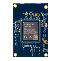
Illustrative top and bottom views of the module for reference.
Recommended conditions for storing the module, including temperature, humidity, and shelf life.
Guidelines for manufacturing processes, including solder paste application and reflow soldering profiles.
Specifications and process details for module packaging, including reels and cartons.
List of related documents for further reference.
Glossary of terms and abbreviations used throughout the document.
| Brand | Quectel |
|---|---|
| Model | SC206E Series |
| Category | Control Unit |
| Language | English |
