Ⅲ. Connection and fix
5
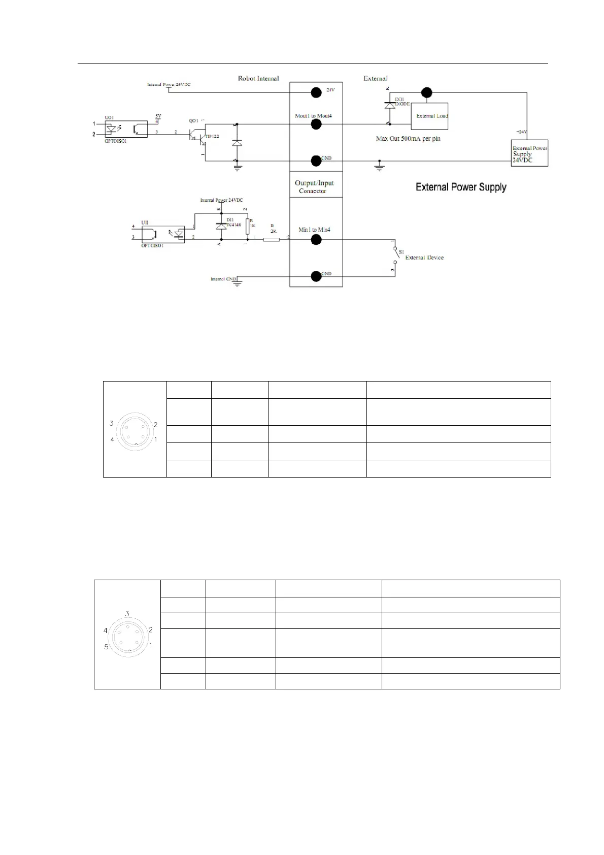
3.2.2 Pins Instruction of Four-pin Socket
The following list describes the pins function of the four-pin socket.
3.2.3 Pins Instruction of Five-pin Socket
The following list describes the pins function of the five-pin socket. By the socket, it can connect with
photoelectricity switch etc.
NOTE:
Input3&Input4 are set at Effective Level window. INPUT0 is corresponding socket number of PCB.
Pin NO.
Pin’s Name Instrution of Pins Application
1 24VDC “+” power supply Output signal
2 GND Ground of power supply
3 INPUT0 signal input 3
connect with sensor, such as photoelectricity
switch
4 FOOT2 signal input 4 Connect with cylinder
5 NC NULL
Pin No.
Pin’s Name
Instrution of Pins Application
1 FOOT1
Now used to connect with “
START/STOP”.
2 GND Ground of power supply
3 INPUT1
Now used to reset (ORG) signal
4 NC NULL
Internal