Ⅲ. Connection and fix
6
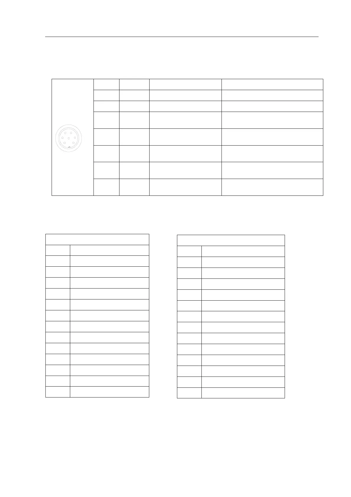
3.2.4 Pins Instruction of Seven-pin Socket
The following list describes the pins function of the seven-pin socket. By the socket, it can control the
external device.
3.4 Soldering Process
After setting parameter, it can start operation, and the movement process is as following table.
Working process
0 Clean point (If set)
1 Home Point
2 1st Height
3 1st Feeding
4 Work Point
5 1st Delay
6 2nd Feeding
7 2nd Delay
8 3rd Feeding
9 3rd Delay
10 4th Height
11 4th Feeding
12 4th Delay
13 Home Point
Clean process
1 Clean point ( Home Point)
2 1st Height
3 1st Feeding
4 1st Delay
5 CLEAN
6 2nd Feeding
7 2nd Delay
8 3rd Feeding
9 3rd Delay
10 Clean delay
11 4th Height
12 4th Feeding
13 4th Delay
14 Clean point ( Home Point)
1
2
3
4
5
6
7
Pin NO.
Pin’s name
Instrution of pins Application
1 24V “+” power supply Output
2 GND Ground of power supply
3 Mout1
Main signal output1, the current
is less than 0.5A
Now used to feeding signal
4 Mout4
Main signal output4, the current
is less than 0.5A
Now used to cylinder
5
INPUT1
(the function is same with the 3
rd
pin of four-pin socket )
Now used to reset (ORG) signal
6 Mout2
Main signal output2, the current
is less than 0.5A
Now used to output working state signal
7 Mout5
Main signal output5, the current
is less than 0.5A
In effective only when pulse signal inputting