118444 Rev. D
19
QM-710/71 5HD/72 0
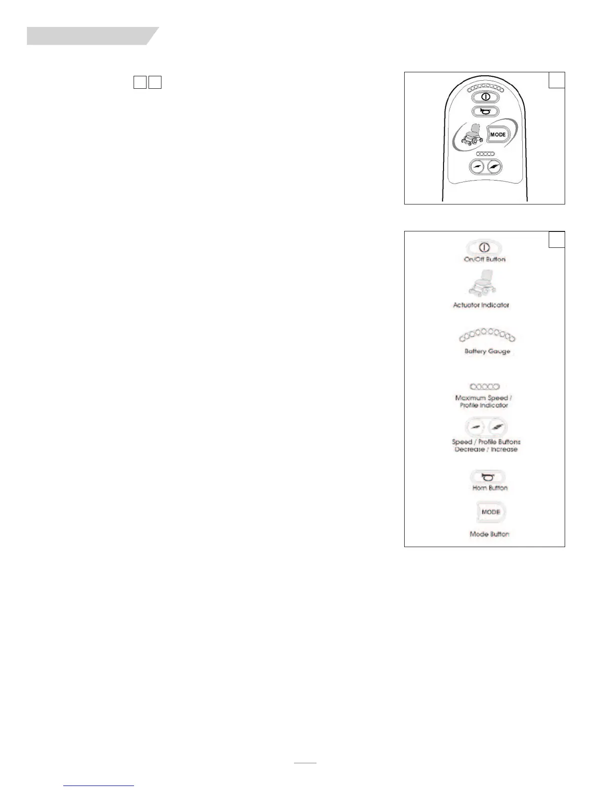
D. LED JOYSTICK
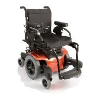
On/Off Button
The on/off button applies power to the control system electronics, which in turn supply
power to the wheelchair’s motors. Do not use the on/off button to stop the wheelchair
unless there is an emergency. (If you do, you may shorten the life off the wheelchair drive
components.)
Horn Button
The horn will sound while this button is depressed.
Battery Indicator
This displays the charge available in the battery and alerts the user when the charge level is
low.
• Steady: This indicates that all is well
• Flashing Slowly: The control system is functioning correctly, but you should charge the
battery as soon as possible.
• Stepping Up: The wheelchair batteries are being charged. You will not be able to drive
the wheelchair until the charger is disconnected and you have switched the conrol sys-
tem off and on again.
• If the battery gauge shows red, yellow and green, the batteries are charged (bars 1 - 10).
• If the battery gauge shows just red and yellow, then you should charge the batteries as
soon as you can (bars 1 - 7).
• If the battery gauge shows just red, then you should charge the batteries immediately
(bars 1 - 3).
Maximum Speed/Profile Indicator
This is a gauge that shows the maximum speed or profile setting of the wheelchair. There are
five speed/profile settings– step 1 is the lowest speed and step 5 is the highest.
• Speed level active is indicated on display by a series of five lights. One light indicates
slowest level currently active, while five lights indicates highest level currently active.
• Drive mode is indicated by a single light. The first light indicates Drive Mode 1; the sec-
ond light indicates Mode 2, and so on.
Speed Decrease Button
This button decreases the maximum speed setting or, if the control system is programmed
for drive profile operation, selects a lower drive profile.
Speed Increase Button
This button increases the maximum speed setting or, if the control system is programmed
for drive profile operation, selects a higher drive profile.
Mode Button
The Mode button allows the user to navigate through the available operating modes for the
control system. The available modes are dependent on programming and the range of auxil-
iary output devices connected to the control system.
Actuator Indicator
This LED set displays which actuator channel is currently being controlled when the control
system is in Actuator Mode. Actuator selection and operation is achieved using the joystick.
• Motions to the LEFT or RIGHT select different actuator channels.
• Motions FORWARD and BACKWARD move the actuator(s) selected.
E. COLOR LCD SCREEN JOYSTICK
This section covers those joystick modules that are fitted with a color LCD screen. The
color LCD screen is split into three areas of information. The Top Bar, the Base Bar and the
Main Screen Area.
18 19
LED Joystick
18
19
IX. CONTROLS, JOYSTICK & OPERATING GUIDE