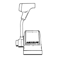
Required Mounting Clearance
(Metric: 1” =
25.4mm)
k4-21/32”
4
,12”
Radius (Minimum)
I/
25067
IMPORTANT: The control cables should extend stralght downward tor at
least 3 ft. (lm) before bendlng, and cable bends should have at least
a
12”
(30.4cm)
radius. This
will
prevent blndlng of cables.
Locating and Drilling
Mounting Area
ACAUTION
Area directly under control must be free of obstruc-
tions (bulkhead, braces, etc.). Cables always must pro-
trude from rear of control, extending straight-down
and parallel to each other. Radius (at point where
cables are routed toward stern of boat) must not be less
than 12”
(30.5 cm).
This will prevent placing a load or
bind on control cables that would result in hard shifting
or binding throttle action.
1.
Locate area where control will be mounted in boat.
Be sure to allow sufficient clearance for control
handle when in full forward and full reverse posi-
tion.
2.
Place Template (provided on last page) over area
where control is to be mounted.
3. Cut and drill mounting area as
plate.
indicated
on tem-
Remote Control Mounting
ACAUTION
This trim control can be connected only to Power
Trims that are equipped with a 2-solenoid trim pump. If
Power Trim is equipped with only one solenoid, a Trim
Solenoid Kit must be purchased and installed on
Power Trim pump.
9-
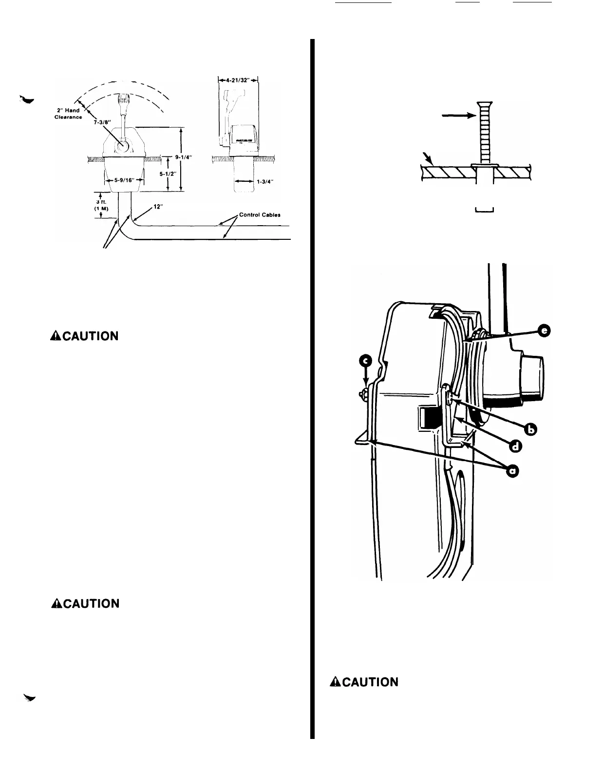
1. Insert
wellnut
fasteners into drilled holes with
flange against the outer surface.
NOTE: It may be helpful to thread a
into fastener when inserting fastener
Mounting Screw
<-+
Mounting Surface
mounting screw
into drilled hole.
Wellnut
it
2.
Install mounting brackets on remote
two
2-1/4”
(57mm) long screws and
shown.
control with
locknuts, as
50129
a
-
Mounting Brackets
b
-
Screws
c
-
Locknuts
d
-
Protective Sleeve
e -Wiring Harness
3.
Make sure wiring harness and protective sleeve are
installed as shown.
ACAUTION
Protective sleeve must be positioned over the wires
and behind the mounting bracket, as shown, to prevent
wires from being pinched or cut by the mounting
bracket.