User’s Manual 125
12.5 Clocked Serial Ports
See Section B.2.3 for more information for more information about a new feature added to
revisions A–C to better support full-duplex communication.
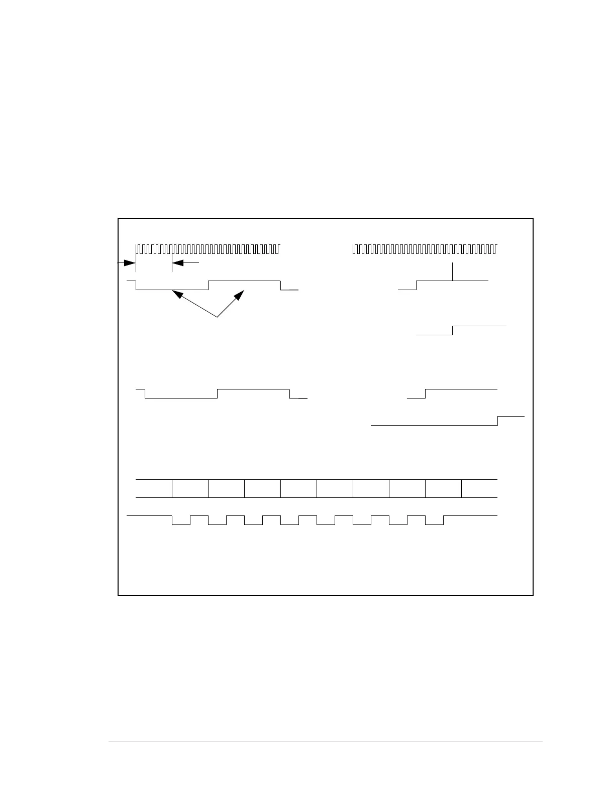
Ports A and B can operate in clocked mode. The data line and clock line are driven as
shown in Figure 12-4. The data and clock are provided as 8-bit bursts. The transmit shift
register advances on the falling edge of the clock. The receiver samples the data on the ris-
ing edge of the clock. The serial port can generate the clock or the clock can be provided
externally.
Figure 12-4. Serial Port Synchronization
start bit
8 clocks
stop bit
Receiver Data
Ready Bit
sampling
point
Serial Port
Input Clock
Asynchronous Receive
Asynchronous Transmit
Transmitter Data Reg Full
Bit 0 Bit 7
SCLK
Synchronous Receive/Transmit
(Transmit clock is input clock/2)