12
R2K 24 - RAD - ING - Inst.Manual - 2002.1_CSA
1. INSTALLATION
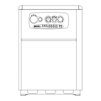
1.1.8. POSITIONING AND
CLEARANCES TO
COMBUSTIBLE MATERIAL AND
SERVICE CLEARANCES
The boiler must be installed only on a vertical solid
wall, able to sustain its weight.
This boiler has been certified to be installed with
“0” clearances to combustible material.
In order to allow the access inside the boiler for
maintenance operations, follow the minimum
service clearances indicated in figure 5.
To facilitate the installation, the boiler is provided
with a jig that allows setting in advance the
connections to the tubes providing the ablility
of connecting the boiler to completed masonry
structure.
To position the unit, proceed as follows (see fig. 6):
1. Trace a line using a spirit level (min. length 9.8 inch) on the installation wall.
2. Place the top of the jig along the traced line respecting the distances of the water connections; then
mark the two points to insert the fasteners, then trace the points for the exhaust vent;
3. Remove the jig and drill the wall;
4. Fix the wall bracket using the screws provided. Hang the unit on the bracket.
3
1
42
70 80 10249 3178
Ø80
Ø125
Ø100
35826 26
54 54
821
681
699
302
785
H
B
A
Y
X
INSTALLATION
A - 7.8 inch
B - 11.8 inch
X - 0 inch
Y - 0 inch
H - 13 inch
fig. 5
fig. 6
 Loading...