23
R2K 24 - RAD - ING - Inst.Manual - 2002.1_CSA
1. INSTALLATION
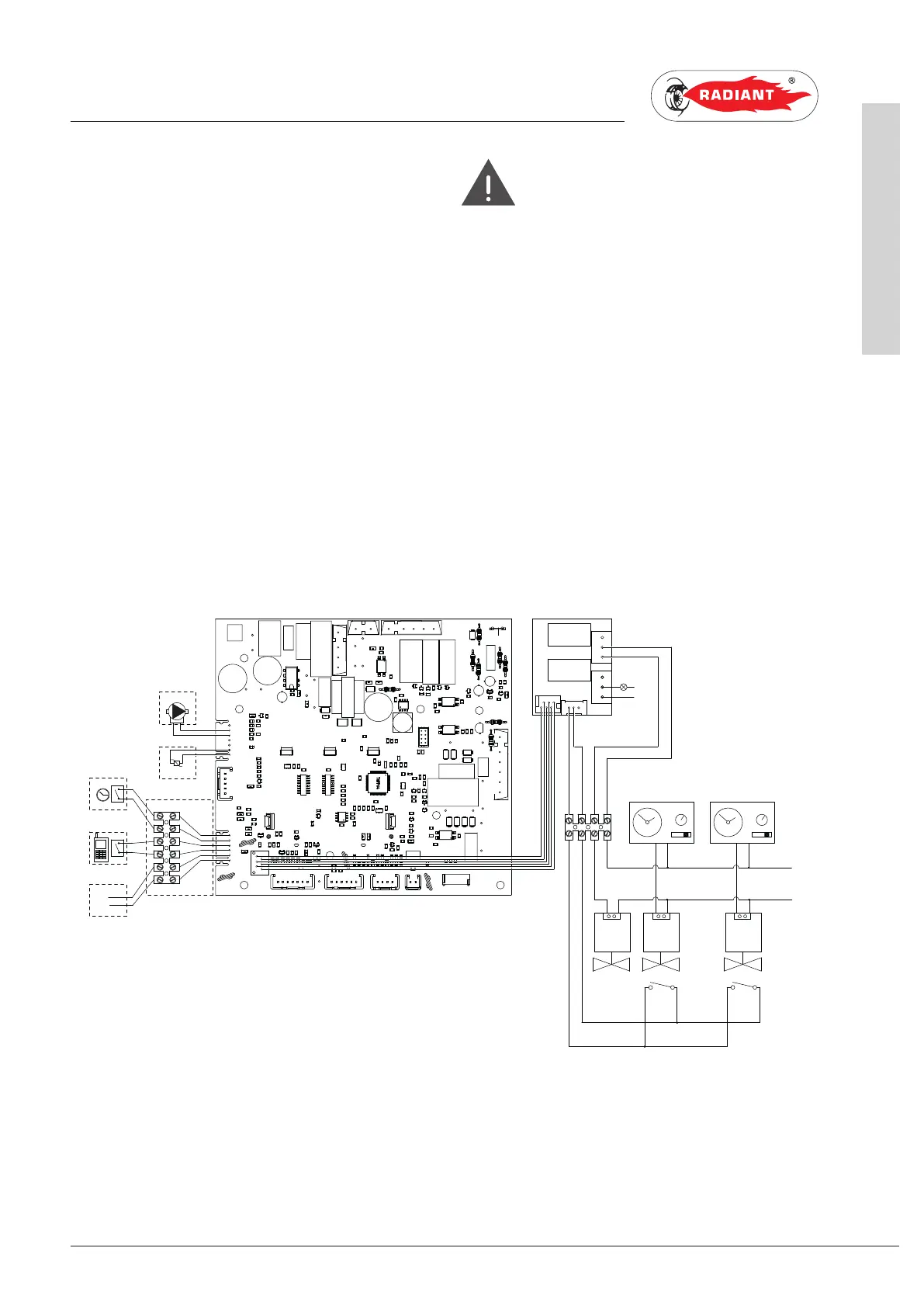
To wire the options below:
• (PM) MODULATING PUMP
• (TP) DOMESTIC HOT WATER PRE-HEATING
DEACTIVATION TIMER
• (CT) TELEPHONE DIALER
• BUS 0-10V
• (SVZ) CONTROL BOARD FOR AREA VALVES
CONNECTED TO A REMOTE CONTROL COD. 65-
00030
Use the electronic board placed inside the control
panel as follows:
DANGER
Shutoff the voltage from the main switch.
› Remove the boiler's front casing (refer to 2.2.13
ACCESSING THE BOILER).
› Remove the crankcase of the control panel (see
2.2.14 ACCESSING THE ELECTRONIC BOARD).
› After removing the crankcase, connect the
items below to the electronic board (see fig. 18):
After performing these operations, remount the
crankcase and the front casing.
TP
CT
BUS 0-10V
GND
BUS+
11
10
98
7
12
13
14
15
16
17
M12
M9
M7
M5
M2
M4
M8
M10
M15
M16
1
2
3
4
57
61
60
59
58
44
43
42
41
40
39
38
37
36
35
34
33
32
31
30
29
28
27
26
MIAH4
ce
ma
PM
SR
62
63
64
65
66
67
68
51
52
53
54
55
56
5
6
M13
M14
ar
ar
ne
ne
ce
ma
220 V - 50 Hz
L
N
VZR
VZ2 VZ1
FC FC
TAZ 2
TAZ 1
SRB
N
1
2
3
4
5
6
9 8
7
M1
M4
M2
M3
SVZ
L
gr
ar
ro
ne
COD.40-00133
fig. 18
SR: RETURN PROBE FC: AREA VALVES LIMIT SWITCH
SRB: REMOTE LED FOR SIGNALLING BOILER LOCKOUT GY: GREY
TAZ1: ENVIRONMENT THERMOSTAT AREA 1 O: ORANGE
TAZ 2: ENVIRONMENT THERMOSTAT AREA 2 BK: BLACK
VZ1: AREA 1 VALVE BR: BROWN
VZ2: AREA 2 VALVE BL: LIGHT BLUE
VZR: REMOTE CONTROLLED AREA VALVE R: RED
INSTALLATION
 Loading...