4. Unsolder
the
contacts
from
the
PCB.
Be
sure
that
the
contact
ends (protruding
through
the
Board) are actually free. This
is
important
when you are working on
double-sided Boards.
5. Note
the
position
of
both
types
of
con-
tacts.
The
fingered
contact
is
usually on
the
right side, with
the
keyboard
oriented
in
a normal position.
6. Using a pair
of
strong needle-nosed pliers,
pull
both
contacts
out
of
the
plastic base.
Fine
pointed
needle-nose pliers usually
cannot
grip
the
thin
contacts
well enough
for
extraction.
7. Insert a new
contact
set
in
tool #773-
10000
or
#773-10023, making sure
that
the
contact
fingers face each
other.
8. Insert
the
tool with
the
new
contacts
into
the
key base. Press
the
tool firmly until it
seats against
the
stops. Insure
that
the
PCB
is
not
resting
on
a hard surface because
the
tool will
try
to
force
the
contact
end
through
the
PCB.
9.
Extract
the
tool. Check
that
the
new con-
tacts
are
in
proper
position and
the
solder
ends
extend
through
the
PCB
on
the
oppo-
site side.
10. Solder
the
contacts. Replace
the
spring,
plunger, and keycap. Check
the
key for
proper
operation.
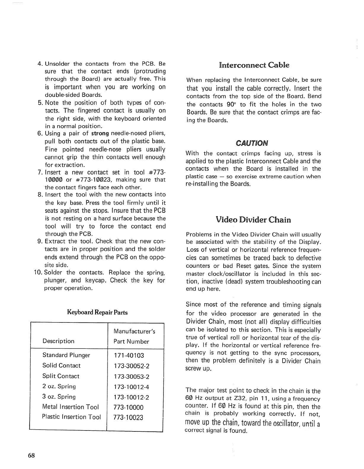
Keyboard Repair Parts
Manufacturer's
Description
Part
Number
Standard
Plunger
171-40103
Solid
Contact
173-30052-2
Split
Contact
173-30053-2
2
oz. Spring
173-10012-4
3
oz. Spring
173-10012-2
Metal Insertion Tool
773-10000
I
Plastic Insertion Tool
773-10023
68
Interconnect
Cable
When replacing
the
I
nterconnect
Cable, be sure
that
you install
the
cable correctly. Insert
the
contacts
from
the
top
side
of
the
Board. Bend
the
contacts
90°
to
fit
the
holes
in
the
two
Boards.
Be
sure
that
the
contact
crimps are fac-
ing
the
Boards.
CAUTION
With
the
contact
crimps facing up, stress
is
applied
to
the
plastic I
nterconnect
Cable and
the
contacts
when
the
Board
is
installed
in
the
plastic case - so exercise
extreme
caution
when
re-installing
the
Boards.
Video Divider
Chain
Problems in
the
Video Divider Chain will usually
be associated with
the
stability
of
the
Display.
Loss
of
vertical
or
horizontal reference frequen-
cies can sometimes be traced back
to
defective
counters
or
bad Reset gates. Since
the
system
master clock/oscillator
is
included
in
this sec-
tion.
inactive (dead) system
troubleshooting
can
end
up here.
Since
most
of
the
reference and timing signals
for
the
video processor are generated
in
the
Divider Chain,
most
(not
all) display difficulties
can be isolated
to
this section. This
is
especially
true
of
vertical roll
or
horizontal
tear
of
the
dis-
play. If
the
horizontal
or
vertical reference fre-
quency
is
not
getting
to
the
sync processors,
then
the
problem definitely
is
a Divider Chain
screw up.
The
major
test
point
to
check
in
the
chain
is
the
60
Hz
output
at
Z32, pin 11, using a frequency
counter.
If
60
Hz
is
found
at
this pin.
then
the
chain
is
probably working correctly. If
not,
move
up
the
chain,
toward
the
oscillator,
until
a
correct
signal
is
found.

 Loading...


