sourced by D flip-flop
7.1, at pin 6. The flip-flop
disables
the
data
latches
during a
CPU
interruption
of
video RAM.
Notice pin
4 of
Zl
. It is tied to VID*. When VID*
goes
low,
7.1
,
pin
6,
will
go
low. The low
at pin 6 will clear the
data latches. (This
is
what generates
the black streaks we
discussed
in the video RAM addressing
section.) When the
CPU
has
finished
with video RAM, pin
4 of
Z7
goes back
high.
The next
time
data is to be latched
into
Z27
and
Z28,
Z7
will toggle back
to its
normal
reset state and allow the
data latches
to
operate. If Z7 was not
used, we might see
characters
that appear ripped apart
on
the screen. For
example,
assume the CRT was drawing
a character when
the
CPU
took command of video RAM. After
the
CPU
finished, the
video processing circuit may still
see the
ASCII
code
that was in the latch at the time
the
CPU
suddenly
jumped in. The video circuit
would try to redraw the
character
on the screen.
We
would then either see
the
character
twice; or half of it would be over
there, and the
other half would
be
here! Clearing
out the data latch
insures us
that the video processor does not
get
confused.
CHARACTER
GENERATOR
Each
character consists of
a dot matrix. The matrix
is
five
dots
wide by seven dots deep. There
is one dot between
any
two adjacent characters
that are never turned
on. We have
five dots,
a space, five more dots,
a space, etc. Vertical
spacing between adjacent
data is determined by
the fre-
quency
of the dot clock.
(In
the TRS-80,
the dot clock sig-
nal
is labeled
SHIFT.)
The
dot
clock
is oscillator
fre-
quency, in 64 character
format, and 1/2 oscillator
fre-
quency, in 32 character format. Horizontal
spacing between
adjacent dots is
a
function
of scan frequency. In
other
words, each row of
dots
is
aligned along the electron beam's
path across
the
CRT. There
are seven
rows of character
dots and five rows of blanks.
Since each character consists of
a
pattern
of dots, there
must be
some method to determine which
dot should be on
and which
dot
should be
off to form any one character.
The character generator controls
the dot patterns on the
screen.
Z29 is the character
generator.
The
seven bit ASCII
word,
stored in the data latch, is applied
to
Z29's ASCII inputs,
pins 1 through 7. The ASCII addresses
a certain area in
Z29. You
might consider the ASCII inputs
to be the higher
seven bits of an address. The lower
part of the address is
inputted
at pins
8,
10
and 11. This three bit
input selects
the
row position of the addressed dot
pattern.
Z29
outputs
five
dots at one
time. Since
each character consists
of
seven
rows of
five
dots, the character generator
must
output
seven separate times just
to
build
one character. Here is
how a typical character line is written: Assume
an ASCII
word
is in the latch. The electron
beam is on the first scan
line of the character. Hence,
pins
8,
10 and 11 have
a
binary
"0"
applied
to them.
Z29
outputs the first
dot
pattern for that particular
ASCII
character. The
next
ASCII
character is applied to Z29. It outputs
the
first
five
18
dots for
that character. This process
goes on until the beam
has scanned
the entire
width of
the screen. If we could
stop
action
at this point,
all you
would have would be a line of
dots. On the second scan line, the data at pins
8,
10
and
11 is incremented to read binary
"1"
(001).
The RAM is
now
prepared to read
the second row
of dots. The first
ASCII character is applied, and it will output the second
row of dots for that character. The second ASCII
word
comes
in, and the
second
row
of
dots go out. This process
continues until all 64 characters
have had the second row
outputted
under the first row of dots. The line counter
increments
and we apply the
first ASCII
word once more.
We paint a row of dots, increment the line counter
and
paint another row. Any character in a line is accessed
at
least seven times. Once the line counter
has gone past the
seventh count, all
the dots make sense; and we will recog-
nize
the dot patterns as characters.
After the seven dot
scans are outputted,
the
electron beam is
turned off; and
five
rows of blank dots are outputted. We would
now
be
ready
to output the
first
row of
dot
patterns for the second
character line.
The
dot output
appears
slow-reading
about
it.
But
ASCII is
being
shot into the character
generator
at
about
a
1.77 MHz
rate. The CRT
and
the
retention
of the eye make these
characters
seem like they
are
outputted
whole.
GRAPHICS
GENERATOR
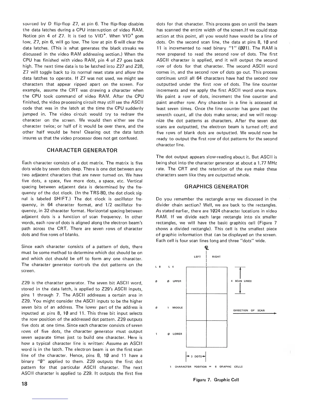
Do you remember
the rectangle array we discussed in the
divider chain
section? Well, we are back to the rectangles.
As stated earlier,
there are 1024 character locations in video
RAM. If
we divide each large rectangle
into
six smaller
rectangles,
we will have the basic graphics cell (Figure 7
shows a divided rectangle). This cell is
the smallest piece
of graphic information
that
can
be displayed on the screen.
Each cell is
four scan lines long and three "dots" wide.
4 SCAN LINES
DIRECTION OF
SCAN
1 CHARACTER POSITION
=
6
GRAPHIC
CELLS
Figure 7. Graphic Cell

 Loading...


