Radio Systems Millenium-A Console Page 19
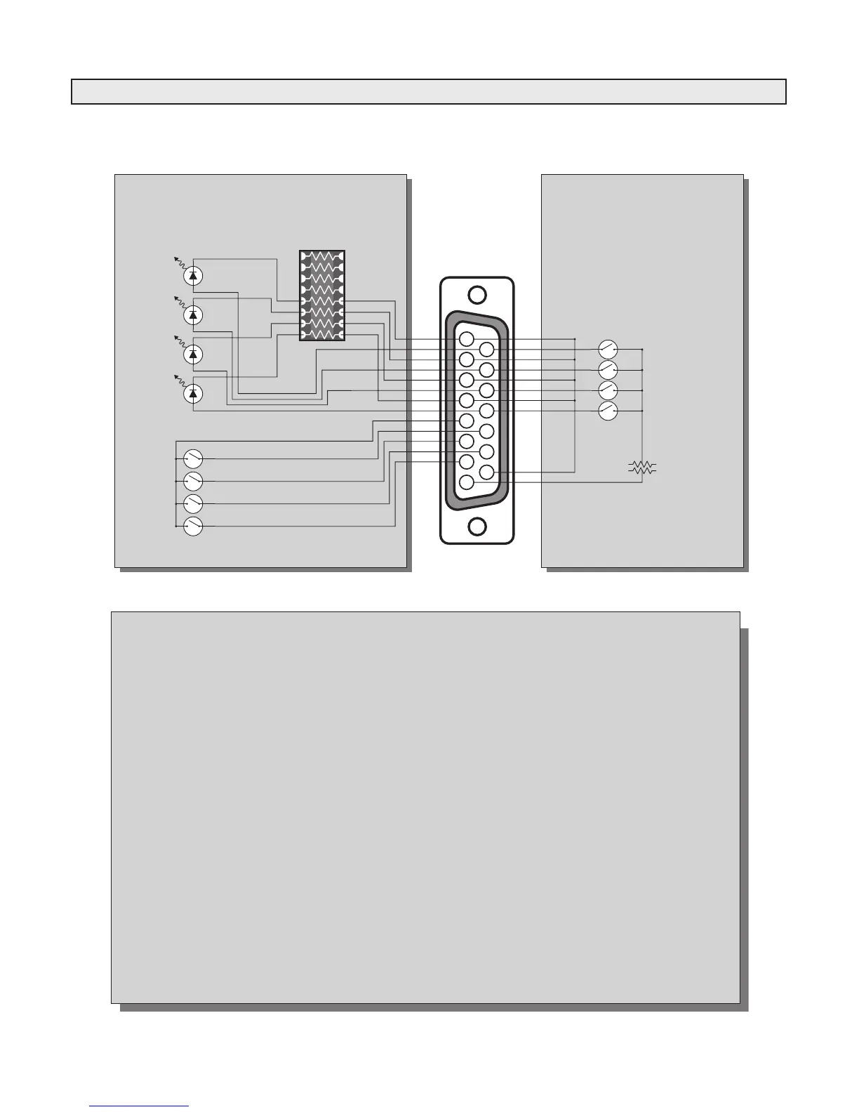
Illustration B-4
Monitor Board Wiring
Console Side Remote Wiring Side
1
2
3
4
5
6
7
8
9
10
11
12
13
14
15
LED 4 Control
LED 3 Control
LED 2 Control
LED 1 Control
Switch 1
LED 4
LED 3
LED 2
LED 1
Switch Common
Switch 2
Switch 3
Switch 4
In-Console
Resistor Socket
(for 15V operation)
Selector Connector
(1 of 2)
Right connector for
switches & LEDs 1-4
Left connector for
Switches & LEDs 5-8
Use console internal 15 Volt power
supply or any external 5 to 15 Volt
supply. In-console resistor socket
must be changed for 5V LED drive.
(Mfg. part#761-3-R680, R.S. part#11157) (Mfg. part#761-3-R680, R.S. part#11157)
Function Descriptions
Pin # Function
1 LED 4 Cathode Lead
2 LED 3 Cathode Lead
3 LED 2 Cathode Lead
4 LED 1 Cathode Lead
5 Switch Common Lead
6 Switch 2 N.O. Lead
7 Switch 4 N.O. Lead
8 +15 Volts DC
9 LED 4 Anode Lead
10 LED 3 Anode Lead
11 LED 2 Anode Lead
12 LED 1 Anode Lead
13 Switch 1 N.O. Lead
14 Switch 3 N.O. Lead
15 Ground
Notes
Install the optional Radio Systems logic card (part number 11027) to add push-on/push-o, exclusive, and lamp follow functions
to the selector buttons.
LEDs are factory set for 15 Volt operation. To change to 5 Volt operation, exchange the resistor dip package located just under the
two selector "D" connectors. For 5 Volt operation, install the 330ohm package included in the accessories package (Mfg.
part#761-3-R220, R.S. part#11158). For 15 Volt operation, re-install the 680 ohm resistor package (Mfg. part#761-3-R680, R.S.
part#11157).