EasyManua.ls Logo

RadioLink R9DS User Manual

RadioLink R9DS
4 pages
To Next Page IconTo Next Page
Page #1 background imageLoading...
Page #1 background image
R9DS
(FHSS and DSSS Spread Spectrum)
Radiolink R9DS, 2.4G 9 channels receiver, DSSS and FHSS spread spectrum working
synchronously, use for Radiolink transmitters AT9, AT9S, AT10 and AT10II.
SBUS and PWM signal possible working at the same time.
Two signal working mode:
1. PWM signal working mode:
PWM signal output working mode:red LED indicates PWM signal output, 9 channels totally.

Other manuals for RadioLink R9DS

Question and Answer IconNeed help?

Do you have a question about the RadioLink R9DS and is the answer not in the manual?

RadioLink R9DS Specifications

General IconGeneral
Frequency Range2.4GHz
Channels9
CompatibilityRadioLink AT9, AT10
Operating Voltage4.0 - 10.0 V
SignalPWM
OutputSBUS

Summary

R9DS Receiver Introduction

PWM Signal Working Mode

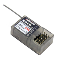
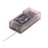
Receiver outputs 9 PWM signals, indicated by a red LED.

SBUS Signal Working Mode

Switching Between PWM and SBUS Signals

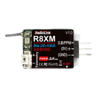
Toggle between PWM and SBUS modes using the ID SET switch; LED color indicates the current mode.

Transmitter Pairing Procedure

Step-by-step guide for binding the R9DS receiver to a compatible transmitter.

Antenna Installation Guidelines

Recommendations for antenna placement to ensure optimal signal reception and range.

R9DS Receiver Specifications

Channel Output Configuration

Describes 9-channel PWM and 10-channel SBUS/PWM simultaneous output modes with LED indicators.

Power and Current Requirements

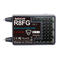
Details the operating voltage range (4.8-10V) and current consumption (38-45mA).

Advanced Features and Connectivity

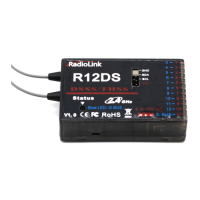
Includes telemetry sensor integration, support for telemetry modules, and high-precision signal output.

Related product manuals