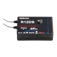
The Radiolink R12DS is a 2.4G 12-channel receiver that utilizes both DSSS (Direct Sequence Spread Spectrum) and FHSS (Frequency Hopping Spread Spectrum) technologies, working synchronously to ensure robust signal reception. It is compatible with Radiolink transmitters such as the AT9, AT9S, AT9S Pro, AT10, and AT10II. For AT9, AT9S, and AT10 transmitters, a firmware upgrade is required to enable 12-channel operation, which can be downloaded from the Radiolink website (www.radiolink.com). The AT10II transmitter defaults to 12 channels.
Function Description:
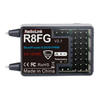
The R12DS receiver offers two primary signal output modes: PWM (Pulse Width Modulation) and S-BUS. It supports simultaneous S-BUS and PWM signal output.
- PWM Signal Output Mode: In this mode, indicated by a red LED, the receiver outputs 11 channels of PWM signal.
- S-BUS Signal Working Mode: When the receiver indicator is blue (or purple), it operates in S-BUS mode, providing a total of 12 channels. In this mode, it synchronously outputs both S-BUS and PWM signals. The S-BUS signal channel (marked in blue on the device) outputs 12 channels of S-BUS signal. Concurrently, PWM signal channels (CH3 to CH12, also marked in blue) output PWM signals, totaling 12 channels. The actual number of available PWM output channels depends on how many S-BUS signal output channels are utilized. For example, if 4 channels are used for S-BUS output, then 8 channels of PWM signal output remain.
Signal Mode Switching:
To switch between S-BUS&PWM and PWM signal output modes, short press the binding button twice within 1 second. A red LED indicates PWM output (11 channels), while a blue/purple LED indicates S-BUS&PWM output (12 channels).
Binding Procedure:
- Place the transmitter and receiver approximately 50 centimeters apart and power both on.
- Switch on the transmitter; the red LED on the R12DS will illuminate.
- Locate the black binding button (ID SET) on the side of the receiver. Press and hold this button for more than 1 second, then release it. The red LED will flash rapidly, indicating that the binding process is underway.
- Once the red LED stops flashing and remains steadily on, binding is complete. A signal tower icon will appear on the transmitter's screen.
Note on Channel Quantity:
After upgrading the transmitter firmware, the channel quantity (for AT9/AT9S/AT10/AT10II) must be changed from 10 to 12 to properly function with the 12-channel R12DS receiver. This modification is done via the transmitter's menu: Press the Mode button to enter BASIC MENU, rotate the dial to select SYSTEM, press Enter, and then change CH-SELECT from 10CH to 12CH.
Antenna Installation:
Proper antenna installation is crucial for optimal performance:
- Antennas should be kept as straight as possible to maximize effective range.
- Maintain a 90-degree angle between the two antennas.
- For large model aircraft with metal parts that might interfere with the signal, position the antennas on both sides of the model to achieve the best RF signal condition across all flying attitudes.
- Keep antennas at least half an inch away from conductive materials like metal and carbon. The coaxial part of the antennas does not need to follow this rule but should not be bent in a small radius.
- Ensure antennas are placed as far as possible from noise sources such as the motor and ESC (Electronic Speed Controller).
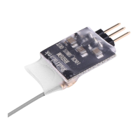
Telemetry Module Connection:
The R12DS supports connection to telemetry modules like the PRM-01 and PRM-03.
- PRM-01: This module provides power return data and integrates with the Radiolink RC system.
- PRM-03: This module, often a flight controller like the Mini Pix from Radiolink, allows for extended telemetry capabilities.
Important Technical Specifications:
- Channels: 11 channels for PWM signal output; 12 channels for SBUS&PWM signal output.
- Working Voltage: 4.8-10V.
- Working Current: 38-45mA (at 5V input voltage).
- Dimensions: 50 x 32 x 14.5 MM (1.97" x 1.26" x 0.57").
- Weight: 14g (0.49oz).
- Integrated Telemetry: The receiver integrates a telemetry sensor for signal strength and voltage.
- Extended Telemetry Support: Supports extended engine voltage telemetry module PRM-01 and PRM-02.
- PRM-02 Functionality: PRM-02 can feedback GPS information, speed, voltage, etc., displayed on AT9/AT9S/AT9S Pro/AT10/AT10II transmitters when working with APM or PIX flight controllers.
- Precision: 4096 section precision, 0.25us per section, with servo anti-shake rudder.
- Control Distance: Approximately 4 kilometers in unobstructed air (maximum range tested in interference-free areas; actual range may vary depending on local regulations).
Usage Features:
- Synchronous DSSS/FHSS: Ensures reliable and robust signal transmission.
- Flexible Signal Output: Offers both PWM and S-BUS outputs, with the ability to use them simultaneously.
- Channel Expandability: AT9, AT9S, and AT10 transmitters can be upgraded to 12 channels via firmware.
- Integrated Telemetry: Provides basic telemetry data like signal strength and voltage directly from the receiver.
- Extended Telemetry: Compatible with external telemetry modules for advanced data like GPS, speed, and engine voltage.
Maintenance Features:
- Shockproof Installation: The receiver can be packed with sponge or foam for shock protection when installed in a model.
- Firmware Upgradable: Transmitters can be updated with the latest firmware for improved functionality and channel support.
- Antenna Placement Guidelines: Detailed instructions for optimal antenna placement to maintain signal integrity and range.
For more information, users can visit the Radiolink website: http://www.radiolink.com.