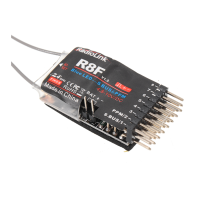
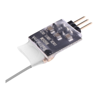
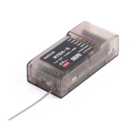
The RadioLink R8F is an 8-channel receiver designed for remote control applications, supporting two-way transmission telemetry and compatible with PWM, PPM, and SBUS signal outputs. This receiver is suitable for various models including cars, boats, fixed-wing aircraft, gliders, and multirotors.
Function Description
The primary function of the R8F receiver is to receive control signals from a compatible RadioLink transmitter and translate them into commands for the model's servos and other components. It operates on the 2.4GHz ISM band, utilizing FHSS (Frequency Hopping Spread Spectrum) technology with 67 channels to ensure robust and interference-resistant communication.
A key feature of the R8F is its two-way transmission telemetry capability. This allows the receiver to send real-time information back to the transmitter, providing critical data such as RSSI (Received Signal Strength Indicator), receiver voltage, and model battery voltage. This telemetry function enhances safety and operational awareness by allowing users to monitor the model's status during flight or operation.
The receiver offers flexible signal output options:
- Standard Working Mode (PWM): In this mode, channels 1 through 8 output PWM signals. Channel 1 is typically used for steering, and channel 2 for throttle. Channels 3 to 8 serve as auxiliary channels for connecting extended functions like light modules, buzzers, or other accessories. This is the default factory setting.
- SBUS/PPM Signal Output Working Mode: This mode is particularly useful for connecting to flight controllers, enabling advanced functions such as RTL (Return to Launch) for shipping boats or complex setups for mecanum wheel models. In this mode, the receiver outputs SBUS and PPM signals, which are commonly used by modern flight controllers.
Usage Features
Compatibility: The R8F is compatible with several RadioLink transmitters, including the 6-channel RC6GS, 4-channel RC4GS, RC3S, RC4G, and the 8-channel T8FB and T8S. To fully utilize the two-way transmission telemetry features, specific firmware versions are required for the RC6GS (V6.0.0 for 3-position switch version ONLY) and RC4GS (V6.0.1 for models produced after January 1, 2018 ONLY). Older models or those with different firmware versions can still bind to the R8F, but the telemetry functions may not be available.
Binding Process: Each R8F receiver has a unique ID code and must be bound to a transmitter before use. Once bound, the ID code is stored in the transmitter, eliminating the need for re-binding unless a new receiver is introduced. The binding process is straightforward:
- Place the receiver and transmitter within 30-50cm of each other.
- Power on the transmitter. The R8F will automatically attempt to bind to the closest transmitter.
- Press the "ID SET" button on the receiver for more than 1 second. The LED on the receiver will flash, indicating the start of the binding process.
- Binding is complete when the LED stops flashing.
- After binding, it is crucial to test the model's servos to ensure proper operation with the transmitter.
Working Mode Selection: The R8F features two LED indicators (RED and BLUE) to signify its current working mode:
- RED LED (always on): Indicates the standard PWM signal output mode.
- RED + BLUE LED (always on): Indicates the SBUS/PPM signal output mode.
To switch between modes, short press the "ID SET" button twice within 1 second. The LED indicator will change from RED to BLUE (or vice versa), confirming the mode transition.
Telemetry Monitoring:
- Signal and RSSI Telemetry: After binding, the signal strength is displayed on the transmitter's homepage. By pressing "EXIT" twice, users can access an interface showing detailed returned information, including the RSSI value. A low RSSI warning can be configured by navigating to the "ALARM" menu (option 19) and setting a desired warning value.
- Model Battery and Receiver Voltage Telemetry: The R8F can return both receiver voltage and model battery voltage in real-time, supporting up to 6S lithium batteries. Users can personalize the low model battery voltage warning value through the "ALARM" menu. For instance, for a 3S lithium battery, a common warning threshold is 11.1V (3.7V per cell * 3 cells).
- Model Battery Voltage Return Connection: This is easily achieved by connecting the male end of a battery wire to the ESC, the female end to the battery, and a JST head wire from the battery to the BAT (+-) port on the R8F. No additional modules are required for this function.
Maintenance Features
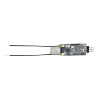
Antenna Installation: Proper antenna installation is critical for maximizing signal transmission and control range:
- Keep antennas as straight as possible to avoid reducing the effective control range.
- Position the two antennas at a 90-degree angle to each other.
- For larger models, especially those with metal parts that can interfere with signal emission, position antennas on both sides of the model to ensure optimal signal reception in all orientations.
- Maintain a minimum distance of half an inch between antennas and any metal conductors or carbon fiber components. Avoid excessive bending of the antennas.
- Keep antennas away from potential interference sources such as motors and ESCs.
Receiver Protection:
- Use sponge or foam material to prevent vibration when installing the receiver, as it contains high-precision electronic components.
- Protect the receiver from strong vibrations and high temperatures.
- Special vibration-proof materials like foam or rubber cloth are recommended for packing the receiver.
- Enclosing the receiver in a well-sealed plastic bag can protect it from humidity and dust, which could otherwise lead to loss of control.
Safety Precautions:
- Avoid operating the model in adverse weather conditions or areas with poor visibility, as this can lead to disorientation and loss of control.
- Never use the product in crowded or illegal areas.
- Always ensure trim levers are at 0 and the battery is properly charged before connecting the receiver.
- Check all servos and their connections before each operation.
- Always turn off the receiver before turning off the transmitter.
- The product is not a toy and is not suitable for children under 18. Adults should supervise children and keep the product out of their reach.
- To prevent water or moisture from entering the transmitter and causing instability, use plastic bags or waterproof cloth to cover the transmitter if operating in wet conditions.
After completing all installation and protection steps, turn off the transmitter and then power it back on to re-test the receiver's binding and functionality.