RadioLink Electronic Ltd
www.radiolink.com
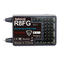
Model battery voltage return can be easily achieved by connecting the male end of the battery
wire to ESC while the female end to the battery and the wire with a JST head connects BAT (+-)
of R7FG/R8F as below pic shown. No extra module is needed.
3. Working Modes
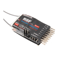
R8F has two working modes:Standard working mode and S.BUS/PPWM signal output
working mode.
3.1 Standard working mode
When the RED indicator is on
,
CH1 to CH8 with PWM signal output , Besides CH1 for steering
and CH2 for throttle , CH3 to CH8 are auxiliary channels to connect extended functions such
as light modules and buzzer and so on
Short press ID SET two times with interval less than 1s, the indicator from RED to
BLUE ,meaning the working mode from PWM working mode to SBUS/PPM signal output
working mode.