Do you have a question about the RadioLink R6F and is the answer not in the manual?
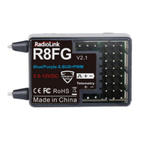
Details the Radiolink R6F receiver's 6-channel capability, gyro integration, HV servo support, and compatible transmitters.
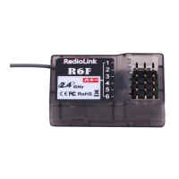
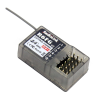
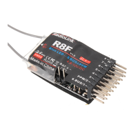
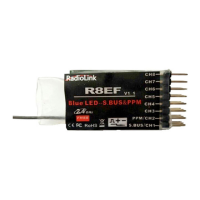
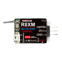
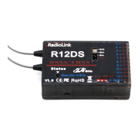
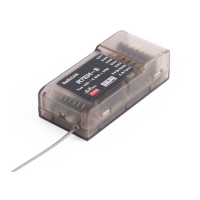
Identifies and explains the function of the receiver's connection ports and the binding status LED.
Step-by-step guide on how to perform the code matching process between the transmitter and receiver.
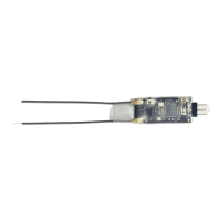
Instructions for installing the receiver antenna correctly.
Instructions for optimal antenna positioning and avoiding interference for effective range.
Detailed list of receiver specifications including frequency, size, weight, channels, power supply, and more.
The RadioLink R6F is a 2.4GHz 6-channel receiver with integrated gyro and HV servo support, designed for use with various RadioLink pistol grip radios and transmitters. It is compatible with the RadioLink 6-channel pistol grip radio RC6GS, 4-channel pistol grip radios RC4GS, RC4G, RC3S, and the 8-channel transmitter T8FB.
The R6F receiver processes signals from the transmitter to control up to six channels, including Rudder (CH1), Throttle (CH2), and four auxiliary channels (CH3-CH6). The integrated gyro provides stabilization, enhancing control for models like cars and boats. It supports high-voltage (HV) servos, allowing for a wider range of servo compatibility. The receiver utilizes GFSK modulation and FHSS (Frequency Hopping Spread Spectrum) for robust and reliable communication within the 2.4GHz ISM band (2400MHz~2483.5MHz).
The green LED indicates the status of the binding process and signal reception. A solid green light indicates a successful bind and good signal.
Proper antenna placement is crucial for maximizing effective range and signal reliability.
Following these steps ensures that the receiver's program functions correctly and maintains a reliable connection with the transmitter.