❖ The sliding boss on the stirrer support I-beam is able to accommodate different sizes of overhead
stirrer rods, with the use of removable adapters. With the adapter in place, stirrer rods of up to
13.5mm diameter can be accommodated. Removal of the adapter (by gently prising from the hole
with a suitable implement) allows stirrer rods of up to 16.5mm to be used.
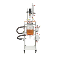
Loosen the locking knobs on the stirrer support I-
beam and slide it down until the coupling pins on
the stirrer drive coupling engage with the coupling
pins on the metal cap of the stirrer guide below.
Note: Only the pins of the two components should
be in contact with each other. Ensure that the
body of the stirrer drive coupling isn’t in contact
with the pins of the stirrer guide.
Retighten the locking knobs on the I-beam.
→ You may need to adjust the position of the overhead stirrer to ensure the pins on the stirrer drive
coupling are perfectly aligned with the stirrer guide. The sliding boss on the stirrer support I-beam
allows the overhead stirrer to be moved forwards, backwards, upwards, downwards, left or right.
Whenever making adjustments to the position of the sliding boss, you should manually support
the weight of the overhead stirrer to allow free movement of the sliding boss.
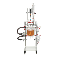
Reposition the two safety stop collars so that they
are located directly below the I-beam. Hand-tighten
the locking knobs to secure.
Note: To check that the pins on the stirrer drive
coupling are correctly aligned with the pins on the
stirrer guide, switch on the power to the overhead
stirrer and start the stirrer motor as slowly as
possible.
 Loading...