Weather Station - Model “PRO”
Nov., 2001 Page 34
Model “PRO”- Weather Station
Cozz GT27145B
“down” toward the datalogger housing.
Then carry the strap across the back of
the bracket and thread it to the front of
the bracket through the far right slot of
the lower set of slots.
Slide the bracket flange, with the three
screw slots, under the heads of the three
(3) mounting screws you have partially
installed in the holes on the left side of
the datalogger housing. With the
bracket fully seated tighten the three (3)
screws to secure the mounting bracket to
the datalogger housing.
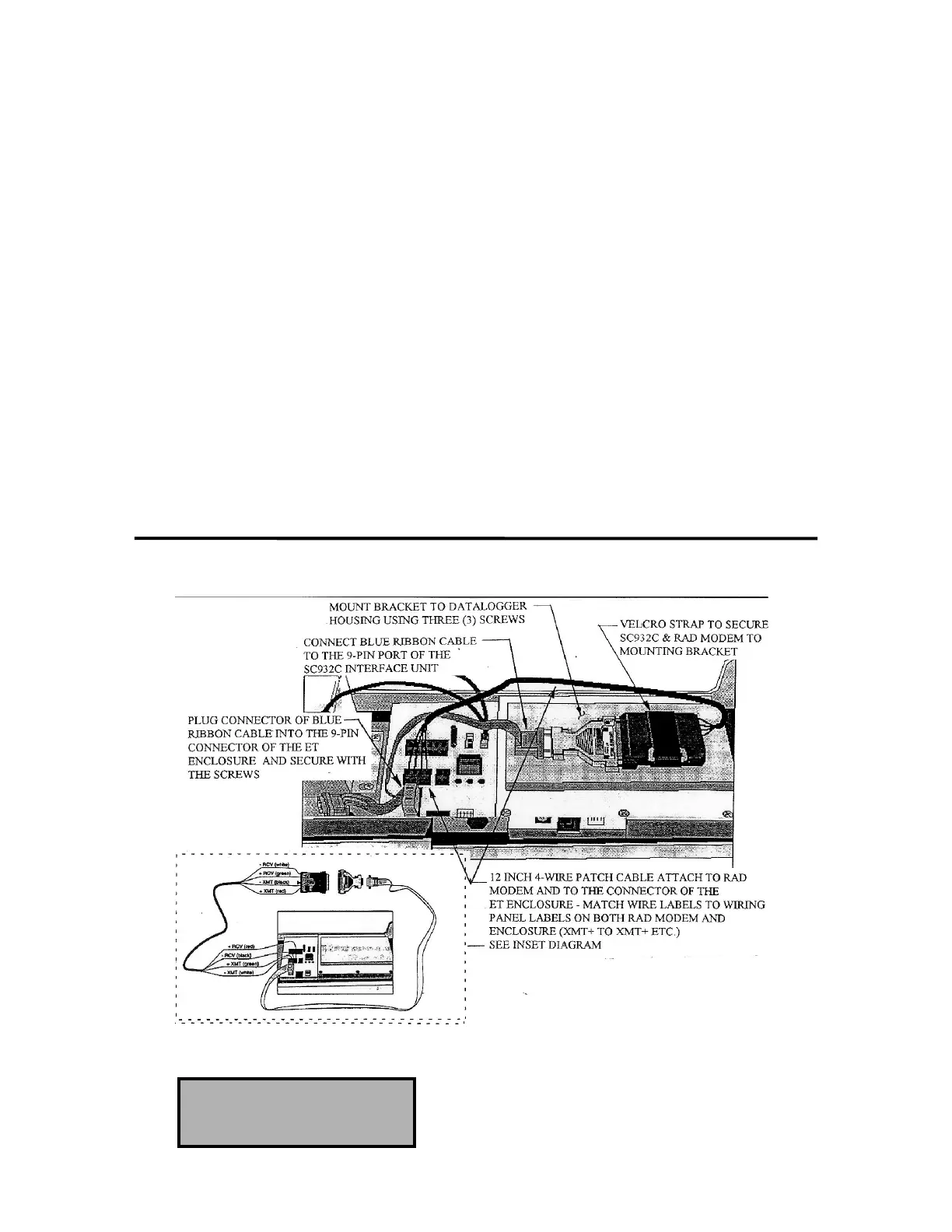
Connect the SC932C Interface to the
RAD Modem. Position this assembly
on the mounting bracket with the
SC932C Interface pointing “down”.
Strap the SC932C Interface unit securely
to the mounting bracket, using the
Velcro strap.
Connect the SC932C 9-pin port to the
internal Enclosure 9-pin port (located
just below the Phone Modem port) using
the blue ribbon cable provided.
Wire the RAD modem to the Enclosure
with the 12 inch 4-wire patch cord
provided. Black (-XMT) wire to -XMT
connections at the RAD modem and at
the connector on the Enclosure. The
RED (+XMT) wire to the +XMT
connections, the White (-RCV) wire to
the -RCV connections and the Green
(+RCV) wire to the +RCV connections
at the RAD modem and at the terminal
blocks: RED to +RCV, Black to -RCV,
Green to +XMT, White to -XMT.
FIGURE 18 - SH MODEM INSTALLATION IN ET ENCLOSURE
TELEPHONE MODEM
INSTALLATION