Weather Station - Model “PRO”
Model “PRO” - Weather Station
Page
61
Nov., 2001
GT27145B Cozz
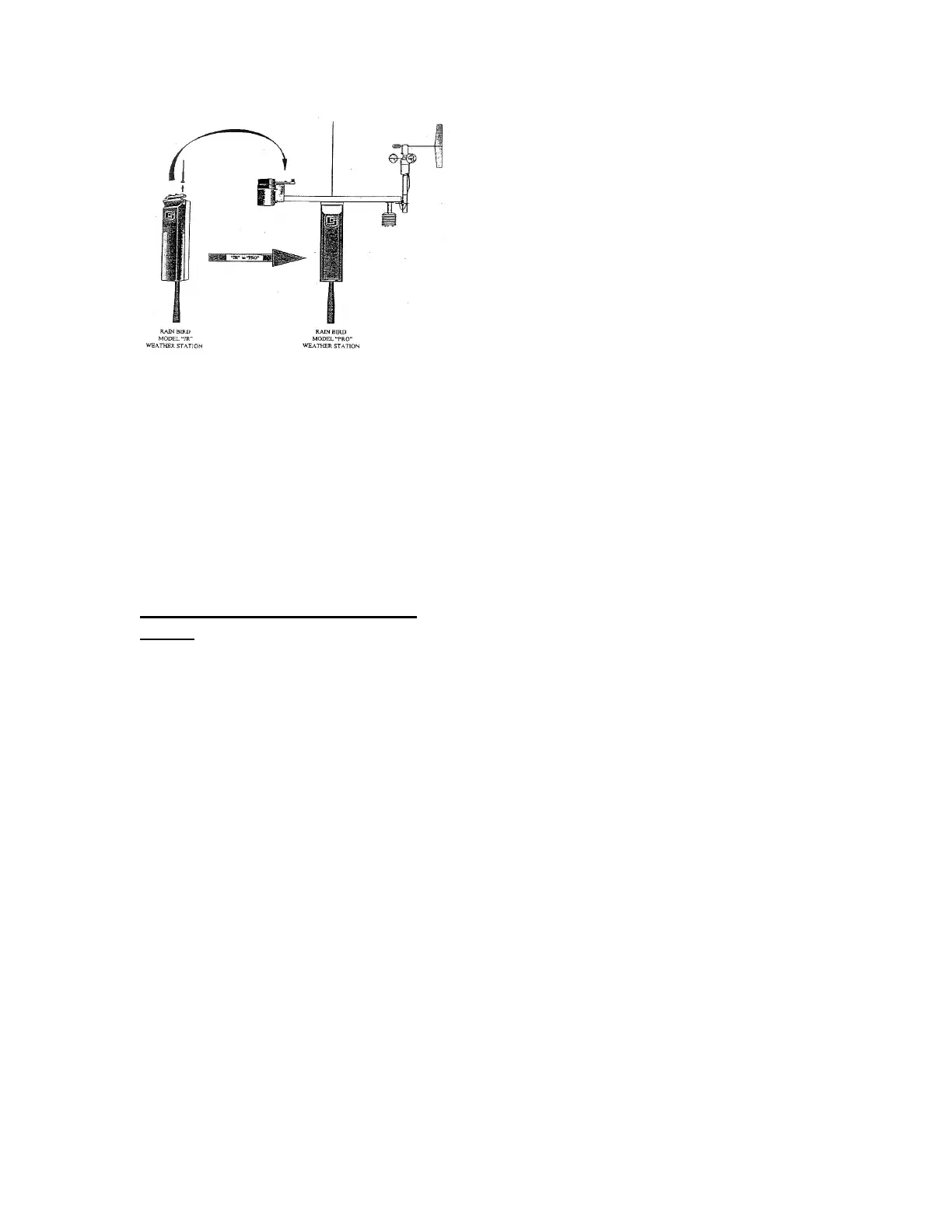
FIGURE 27 - UPGRADE KIT
TYPICAL 3-ROD GROUNDING
GRID:
Grounding grids are required at the
Central equipment location, for the
weather station (grounding grid for the
central equipment may also be used for
the weather station if accessible) and at
the weather station itself.
A typical 3-rod grounding grid shall
consist of three (3) 5/8” diameter x
8’-0” long copper clad grounding rods.
The rods shall be in a triangular
arrangement, if at all possible, with
each rod at least 8’-0” away from any
other rod.(refer to FIGURE 28 below).
If it is impossible to arrange the rods in a
triangular pattern then they may be
arranged in a straight line (although
NOT as effective) with each rod at least
8’-0” from any other rod.
NOTE! If longer than 8’-0” rods are
used, then the rods shall be spaced no
closer than the length of the rod from
each other.
The 3 rods shall be driven into the
ground with top of rod at least six inches
(6”) below the finish grade. The rods
shall be tied together below grade with
#10 gauge or larger bare copper wire.
The wire shall be attached to the rod
using a brass clamp. A separate brass
clamp shall be used for each attachment.
NOTE ! No more than one wire shall be
used in any individual clamp. Multiple
wires shall NOT be allowed.
Any rod that has a ground wire con-
nected to it, coming from the surge
arrestor at the equipment or grounding
the equipment, shall have a standard
18” x 24” rectangular valve box installed
around the top of the rod. This shall
provide future access to inspect and/or
maintain the MGP-1 grounding plate
assembly, MSP-1 pipe surge arrestors,
brass clamp and ground wire should this
be necessary. Any of the other rods in
the grid shall have a standard 6”
diameter round valve box installed
around the top of the rod for future
access.
Where MSP-1 pipe surge arrestors are
required on the communication path
wiring, the MSP-1 pipe surge arrestor
shall be mounted on an MGP-1
grounding plate assembly. The MGP-1
grounding plate assembly in turn shall be
securely attached to one of the grounding
rods of the 3-rod grounding grid.
Attach the MGP-1 to the ground rod that