2
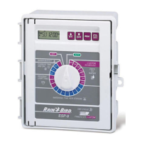
D. STATION TIME CONTROL KNOBS: Individual TIME controls for each station.
Timing is adjustable up to 60 minutes to suit all landscape growth requirements. A
small white arrow moves with each knob along the timing scale on the Station dial (C)
for visual indication of the time setting. The scale is marked-off in 5 minute gradua-
tions and the ratchet action of the knob provides for precision adjustment with each
"notch" representing one minute increments. The OFF position eliminates the station
from the watering schedule. All omitted stations are automatically rapid-advanced to
the next timed station.
E. OPERATIONAL MODE SWITCH: The 2-position MODE switch provides the oper-
ating control for the system, AUTO position for automatic irrigation as scheduled and
"timed" watering of a manually selected station. The OFF position is used for rainy
weather shutdown. This position eliminates controller "output" to the system valves
without interrupting the clock operation.
F. FUSE: 1.5 AMP (Slow Blow fuse) protects the controller from damage due to cur-
rent overload. Replace fuse after the source of trouble has been remedied.
G. CURRENT STATION INDICATOR: STATION indicator identifies the current posi-
tion of controller operation. See control (C).
H. CURRENT TIME INDICATOR: TIME indicator identifies the current time on the
controller clock.
I. CURRENT DAY INDICATOR: DAY indicator identifies the current day of the water-
ing schedule.
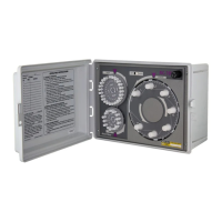
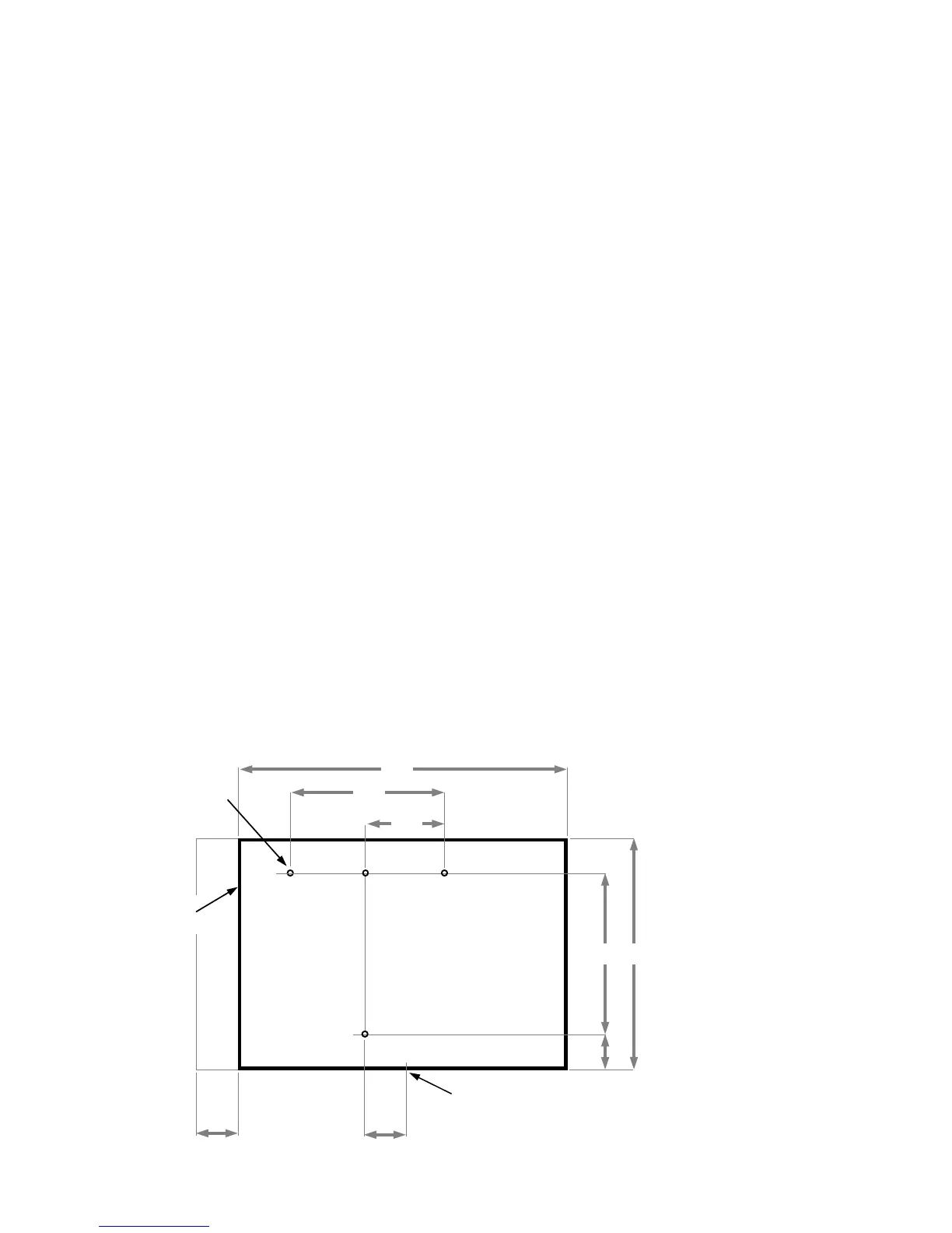
INSTALLATION
The controller is housed in a cabinet suitable for convenient indoor wall mounting.
Four mounting holes are provided through the back surface of the cabinet. Before
mounting the controller, consideration must be given as to accessibility, protection
from water, electrical power source and connections to the system control valves.
11”
7”
3
1
/
2
”
3
1
/
4
” 7
3
/
4
”
2
5
/
8
”
1
3
/
4
”1
3
/
4
”
CONTROLLER
OUTLINE
MOUNTING
HOLES
OPENING
DOOR CLEARANCE
1
5
/
8
” DIA. VALVE WIRE OUTPUT
CONNECTION
Figure 2
CONTROLLER MOUNTING
 Loading...