Basic Operations
R&S
®
ESR
52Getting Started 1316.3749.02 ─ 09
Marker Information in Marker Table
In addition to the marker information displayed within the diagram grid, a separate
marker table may be displayed beneath the diagram. This table provides the fol-
lowing information for all active markers:
Type Marker type: N (normal), D (delta), T (temporary, internal), PWR
(power sensor)
Dgr Diagram number
Trc Trace to which the marker is assigned
Stimulus x-value of the marker
Response y-value of the marker
Func Activated marker or measurement function
Func .Result Result of the active marker or measurement function
Mode-dependant Information in Diagram Footer
The diagram footer (beneath the diagram) contains the following information,
depending on the current mode:
Mode Label Information
FREQ CF Center frequency (between start and stop)
Span Frequency span
SPAN CF (1.0 ms/) Zero span
For most modes, the number of sweep points shown in the display are indicated
in the diagram footer. In zoom mode, the (rounded) number of currently displayed
points are indicated.
The diagram footer can be removed from the display temporarily, see Chap-
ter 6.4.8, "Removing the Diagram Footer", on page 76.
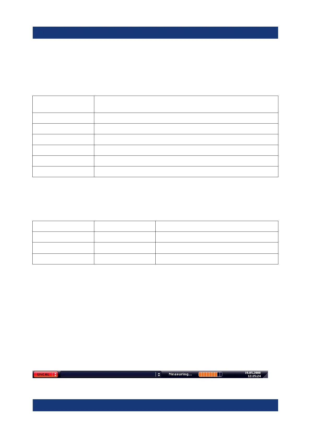
6.1.5 Instrument and Status Information
Global instrument settings, the instrument status and any irregularities are indica-
ted in the status bar beneath the diagram.
Information in the Diagram Area
 Loading...