Preparing for use
R&S
®
NRP Series
21Getting Started 1419.0170.02 ─ 16
Connect the power sensor to the signal source.
2. NOTICE! Risk of sensor damage. Only use PoE power sourcing equipment
(PSE) as described in "Choose the PoE power sourcing equipment (PSE) with
care" on page 15.
Connect the RJ-45 Ethernet connector of the sensor to an Ethernet switch
that supports PoE power delivery.
3. Connect the controlling host to the Ethernet switch.
4. Establish a connection between the power sensor and the network.
See Chapter 3.7.3.2, "Establishing a connection to the network", on page 23.
Setup with a PoE injector and a non-PoE Ethernet switch
HOST
INTERFACE
IN: 3 V or 5 V logic
OUT: min. 2 V into 50 Ω
max. 5.3 V
TRIG2
I/0
PoE
SMART SENSOR TECHNOLOGY
NRP
10
1
2 3 4
5
6
7
8
9
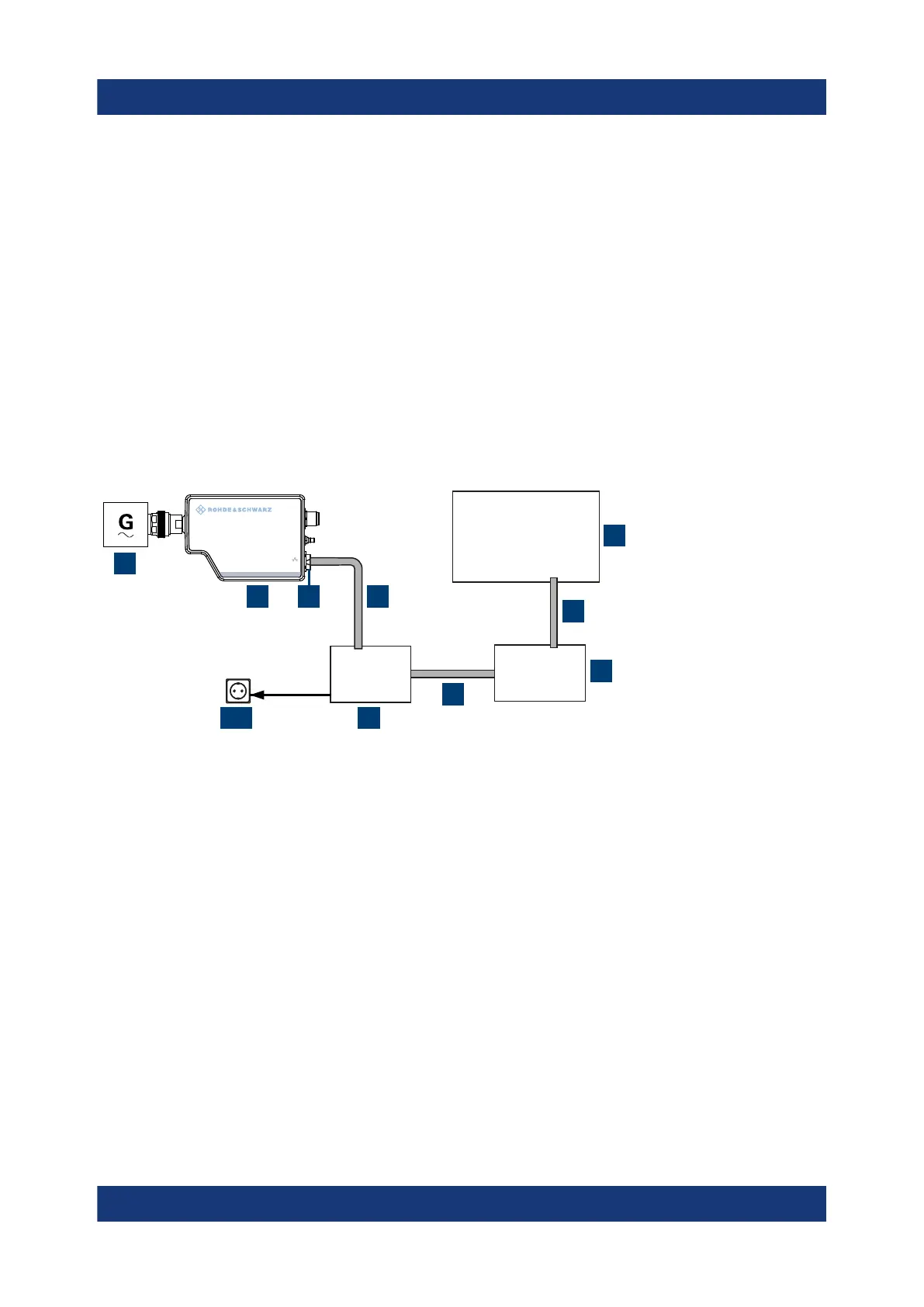
Figure 3-4: Setup with a PoE injector and a non-PoE Ethernet switch
1 = Signal source
2 = LAN power sensor
3 = RJ-45 Ethernet connector
4,6,8 = RJ-45 Ethernet cable
5 = Controlling host
7 = Non-PoE Ethernet switch
9 = PoE injector
10 = AC supply
1. NOTICE! Incorrectly connecting or disconnecting the power sensor can dam-
age the power sensor or lead to erroneous results. Ensure that you connect or
disconnect the power sensor as described in Chapter 3.4, "Connecting to a
DUT", on page 13.
Connect the power sensor to the signal source.
Connecting to a controlling host

 Loading...

